
CVT Guarding
Olin Baja SAE
Skills Advanced: CAD (SolidWorks, Onshape), Sheet Metal Modeling, ANSYS Explicit Dynamics, FEA/Topology/Frequency Studies, Statics, Sheet Metal Fabrication, Lathe, CNC/Manual Mill, Waterjet, Agile, Project Management
Objective: Protect the Continuously Variable Transmission (CVT) on the Olin Baja buggy with a rules-legal cover. Prioritize manufacturability and CVT accessibility/maintenance.
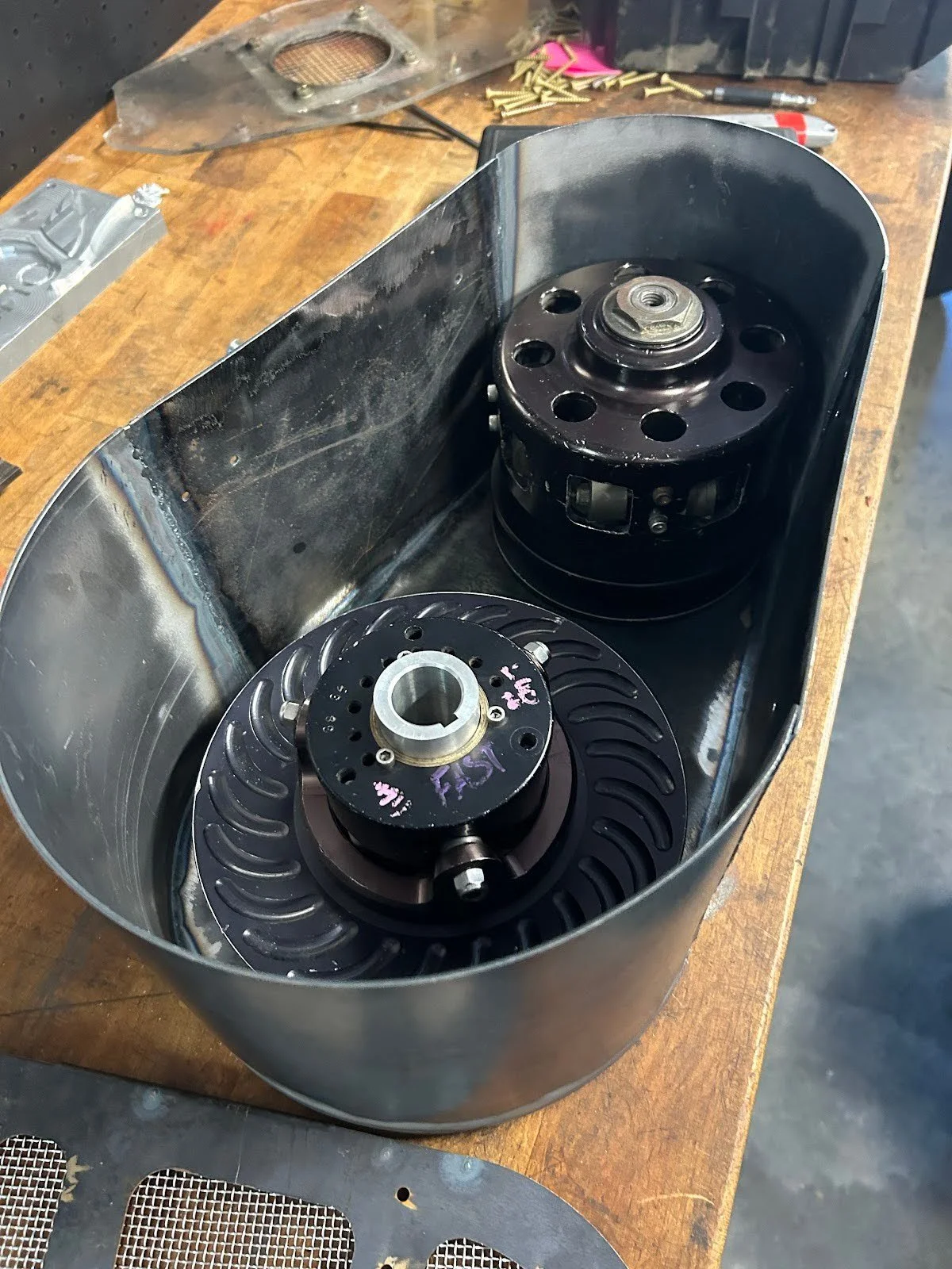
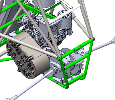
Previous CVT guarding designs on Olin Baja vehicles were extremely restrictive to CVT maintenance. They were unable to be completely removed from the car, and removing the front cover plate was a tedious process that did not allow the CVT to be removed or maintained reliably. In this design, I prioritized full accessibility and removal of the CVT and guarding in as little time as possible, optimizing the powertrain for the fast-paced competition environment.
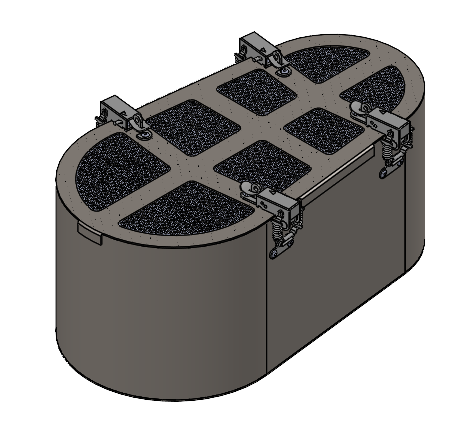


Design:
14 ga. Hot-Rolled Mild Steel Sheet
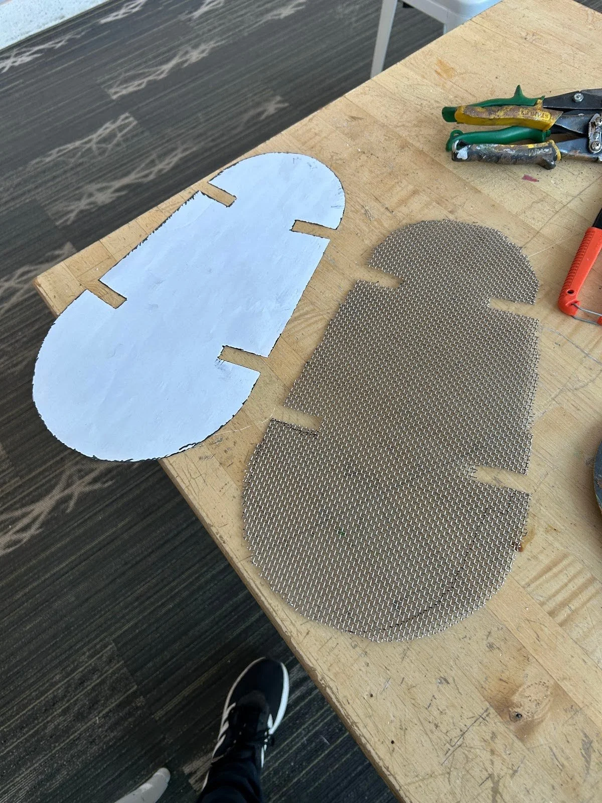
Steel mesh allows airflow while preventing contamination and bodily harm
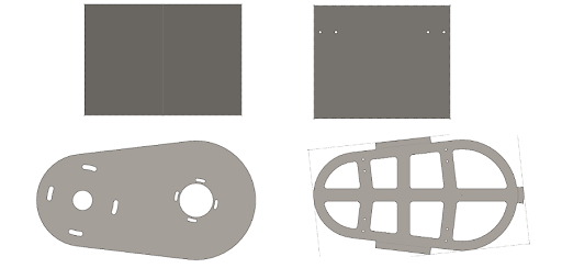
CAD done using SolidWorks sheet metal
Adjustable mounting pattern for assembly adjustments on the fly
Fabrication:
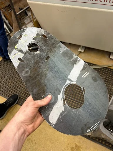
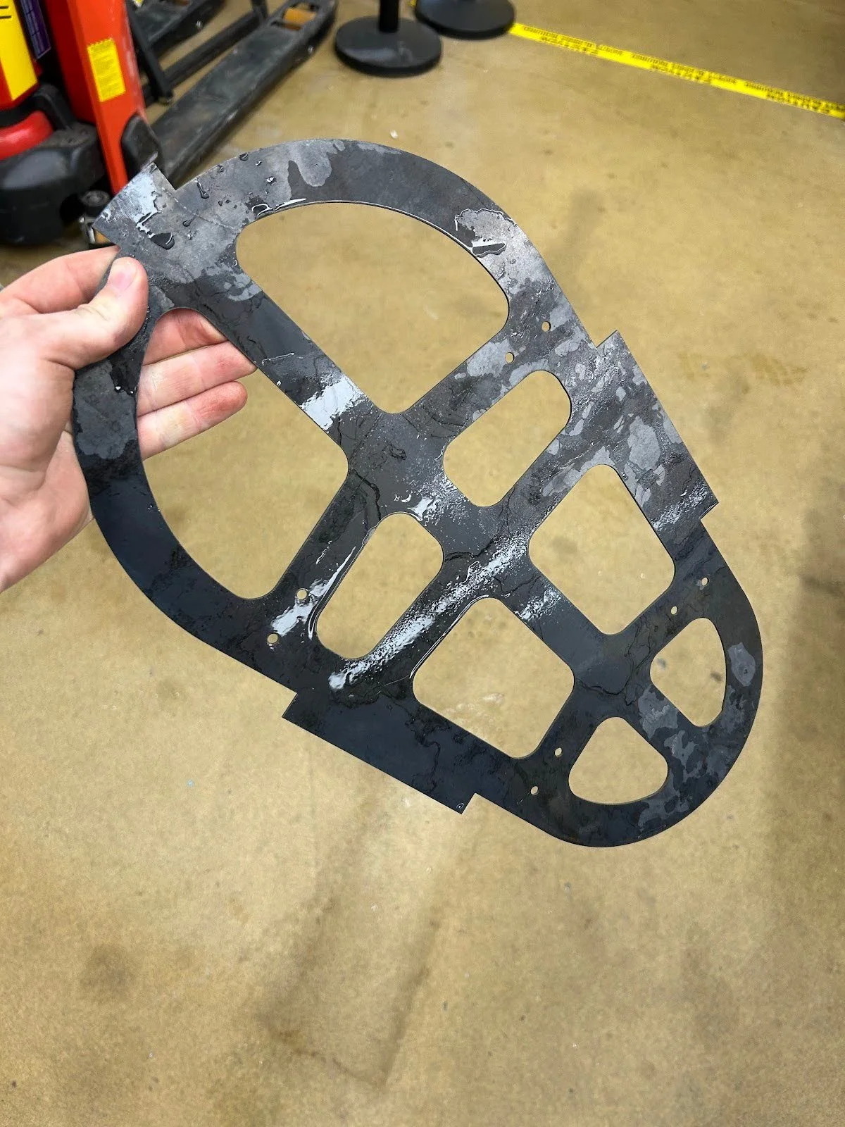
Waterjet front and rear mounting plates
Plasma cut & bend side panels with roller/finger brake
TIG weld permanent guarding together
Spot weld front Mesh
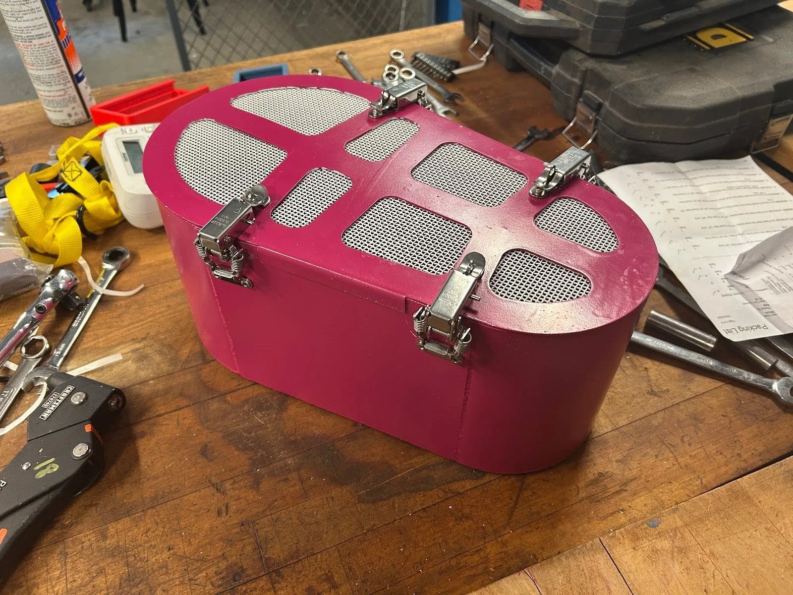
Paint guarding & rivet on the latches
Done!
The most realistic worst-case failure of the CVT, with a high-speed impact on the guarding, would be the ejection of one of the flyweights on the CVT primary at max engine RPM.
Max Engine Speed: 3600 RPM (60 rev/sec)
CVT Primary Radius: 3 in (0.0762 m)
Ejection Velocity: 60 rev/sec × 0.0762 m × 2π 1/rev ≈ 28 m/s (62.5 mph)
Materials: 1010 Carbon Steel (Guarding), C36000 Brass (Flyweight)
Flyweight Mass: 66 g (0.066 kg)
Momentum: 1.848 kg·m/s (comparable to a break shot in pool)
These were the initial conditions used in the simulations. In simulation A, one edge of the guarding was used as the impact zone, with the bottom and side faces fixed to approximate the welded seams in reality. That assumption is more conservative than real life because the impact energy would dissipate further through other panels in reality, but it ensures that the guarding passes a scenario worse than what can be expected in reality. Simulation B uses the entire rear section of the guarding, which is designed for high impact shielding. This more accurately represents a real impact to the guarding since the edges of the impacted panel are bonded to the rest of the guarding rather than fixed, allowing the whole structure to flex as one piece. The reason that this was the only panel I tested was that an item ejected from the CVT primary pulley would only have a direct path to that face. The side panels would deflect the flyweight rather than have a perpendicular impact and the secondary pulley blocks the larger curve.
Simulation A

The new design is comprised of a permanently mounted rear plate and protective hoop with a removable front cover. The permanent guarding bolts to the engine’s PTO shaft face and gearbox casing, ensuring rigid and vibration-resistant mounting. The front plate is attached with 4 sprung, locking latches, enabling full CVT access within 10 seconds, in contrast to the previously inaccessible guarding.

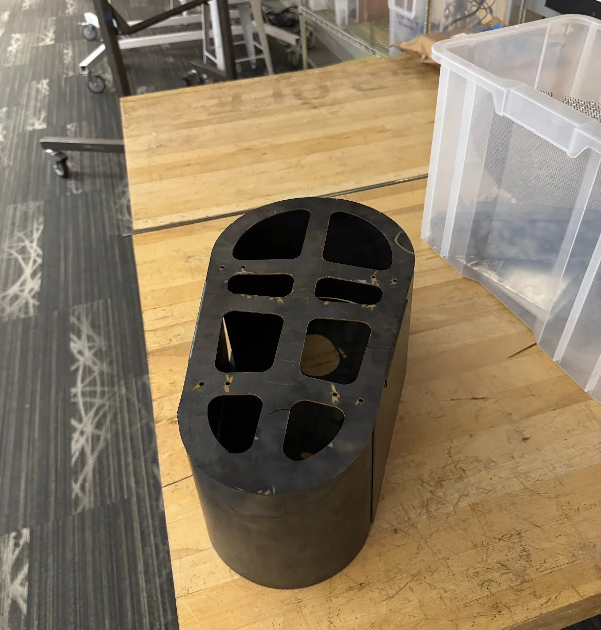
I continue to support this team as one of two Drivetrain Leads. We use the Agile framework for task management, identifying blockers to our progress and determining how to resolve them. I look forward to continuing to build my design, manufacturing, and management skills and expertise with this team!
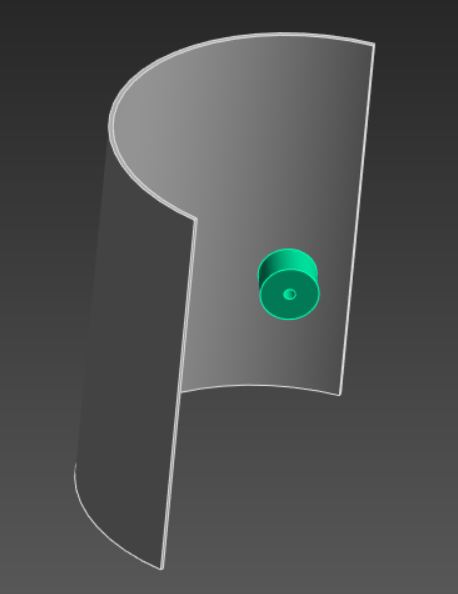
Simulation A of a single guarding section. The flyweight’s initial velocity is toward the center of the panel.
Analysis
Much of the criteria and constraints for the guarding strength arise from the Baja SAE rulebook, but I took the opportunity to check out the worst-case CVT failure on the guarding. Impact simulations were done in ANSYS Explicit Dynamics.
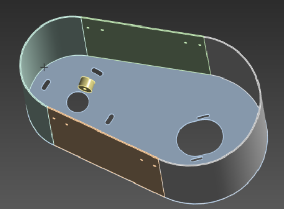
Simulation B of the flyweight and the guard. The flyweight’s initial velocity is toward the middle of the smaller curved section.
Simulation B
Predictably, the guarding experienced significant permanent deformation with stresses far exceeding the yield stress of 1010 steel, with concentrations around the impact zone and fixed faces. However, the weight did not pierce the guarding and was brought to a safe velocity within the confines of the guarding. Because puncture of the guarding or excessive deflection allowing the projectile to escape are the actual unacceptable failure modes of this guarding, rather than just permanent deformation, this guarding is an acceptable design to protect the CVT.