
Noise, Vibration, & Harshness
Flux marine 🔗
Skills Advanced: CAD (SolidWorks), FEA/Frequency Studies, Statics, Fabrication, CNC Milling (316 SS), Engineering Drawings/GD&T, Industrial Design, Arduino, Python, Electronics Potting, Signal Processing
Objective: Quantify and reduce noise and vibration on Flux Marine vessels to improve ride comfort for customers.
Background and Problem Definition
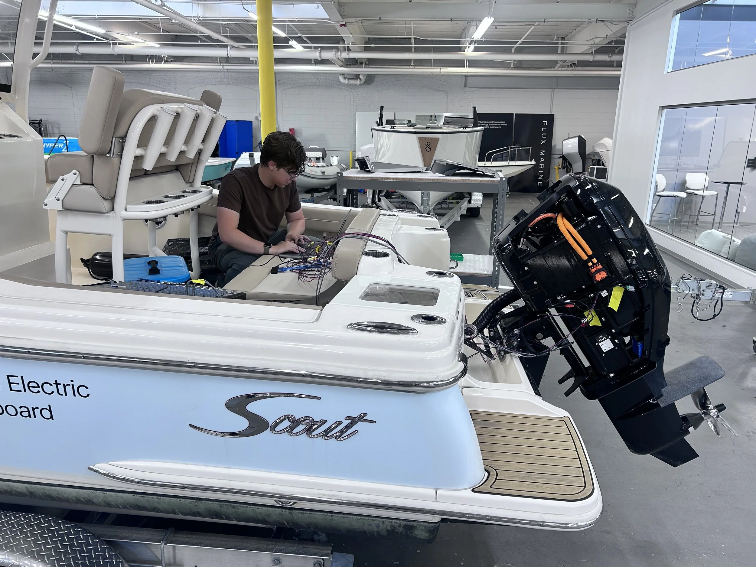
Unsatisfactory noise on one boat, an acceptable reference on another, and limited data on either.
Methods & Materials
2 test methods for NVH quantification: 1 ICOMIA standard and 1 of my own design
Test 1: ICOMIA 39-94 Duty-Cycle Operator Sound Pressure Level
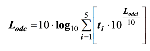
Quantify the equivalent A-weighted operator sound pressure level (SPL) per ICOMIA 39-94 (“Small craft: measurement of duty cycle operator sound pressure level”), computed as a duty-cycle-weighted energy average of steady-state SPL readings across five throttle settings.
Materials
Sound level meter
Tachometer/engine RPM (revolutions per minute) readout
Test Setup
Outboard-powered test boat, underway, steady-state at each throttle setting
Meter position: center console dashboard
Procedure
Power on the sound level meter.
Verify correct operation, using A-weighting and slow response, before testing.
Bring the engine to idle. Allow it to stabilize. Record the steady-state A-weighted SPL at the operator position. Record the actual engine RPM.
Advance to 40% throttle. Hold steady state. Record SPL and actual RPM.
Repeat the advance-hold-record sequence at 60% throttle, then at 80% throttle.
Repeat the advance-hold-record sequence at wide-open throttle (WOT, 100%).
Compute the duty-cycle operator level (Lodc) as the energy-weighted average of the five readings.
Use the ISO 8178 E4 duty-cycle weighting factors (idle 0.40, 40% 0.25, 60% 0.15, 80% 0.14, WOT 0.06):
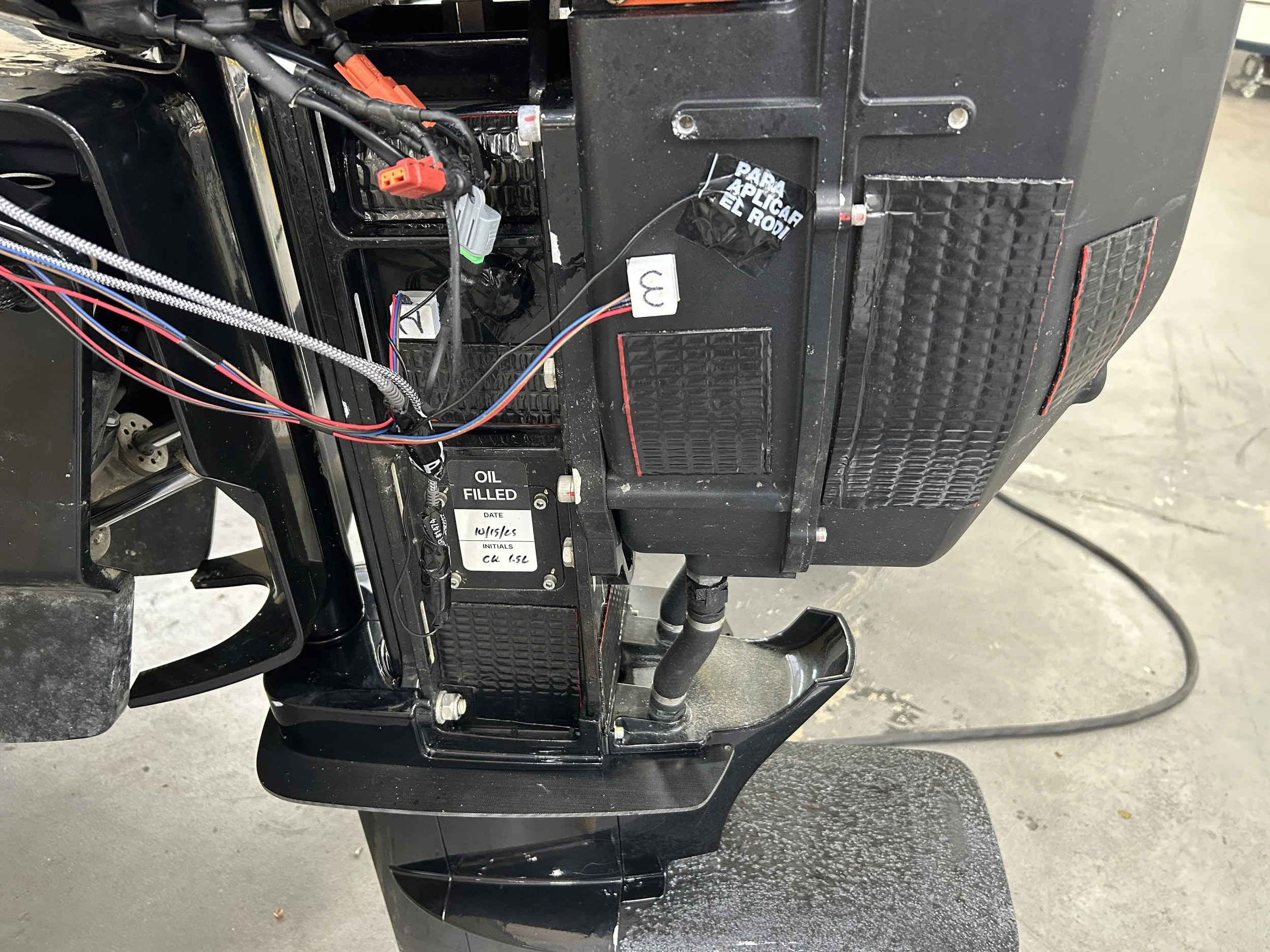
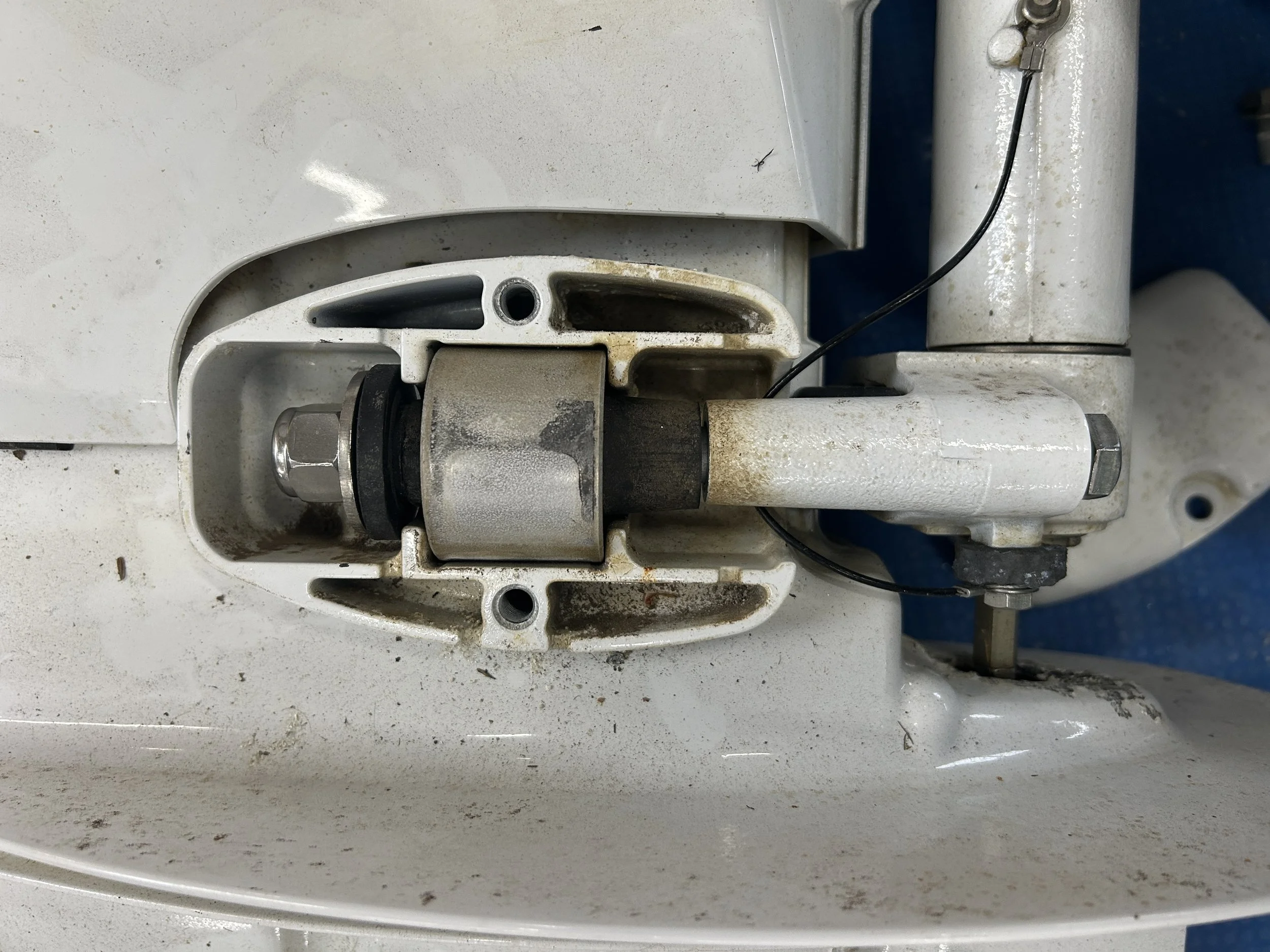
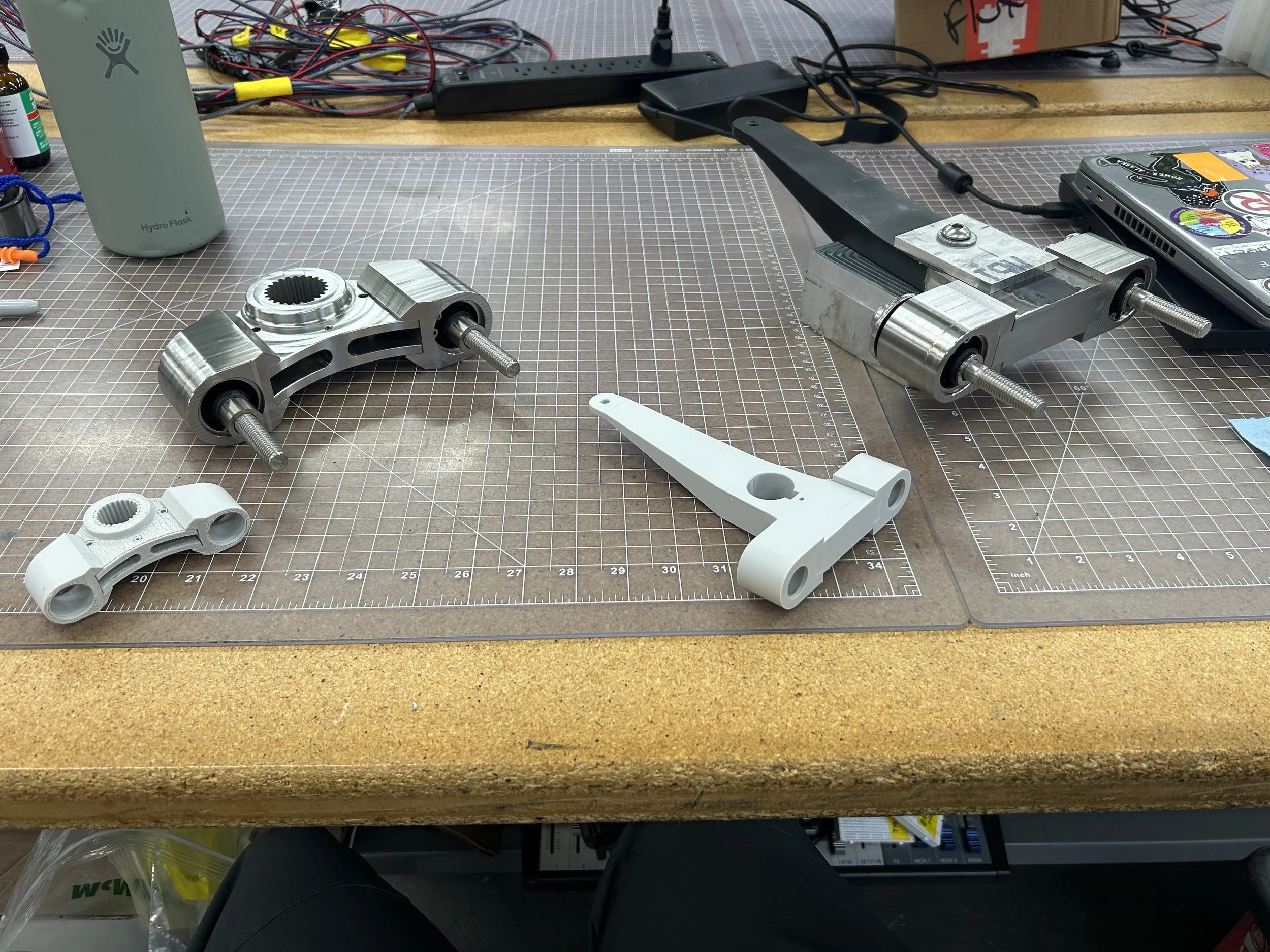
Most OEMs with this mounting method capture the bushings’ OD with a bolted clamshell design. This is simpler to manufacture and assemble, but it's bulky and doesn’t fit within the Flux system's packaging. One constraint for this modification was that the mounting distance from the motor to the transom could not increase, since that would create a longer lever and thus higher torque on the steering hydraulics. This meant I had to get more creative with bushing axial retention. The clamshell design is shown to the right on a Tohatsu ICE outboard.
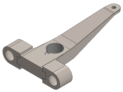
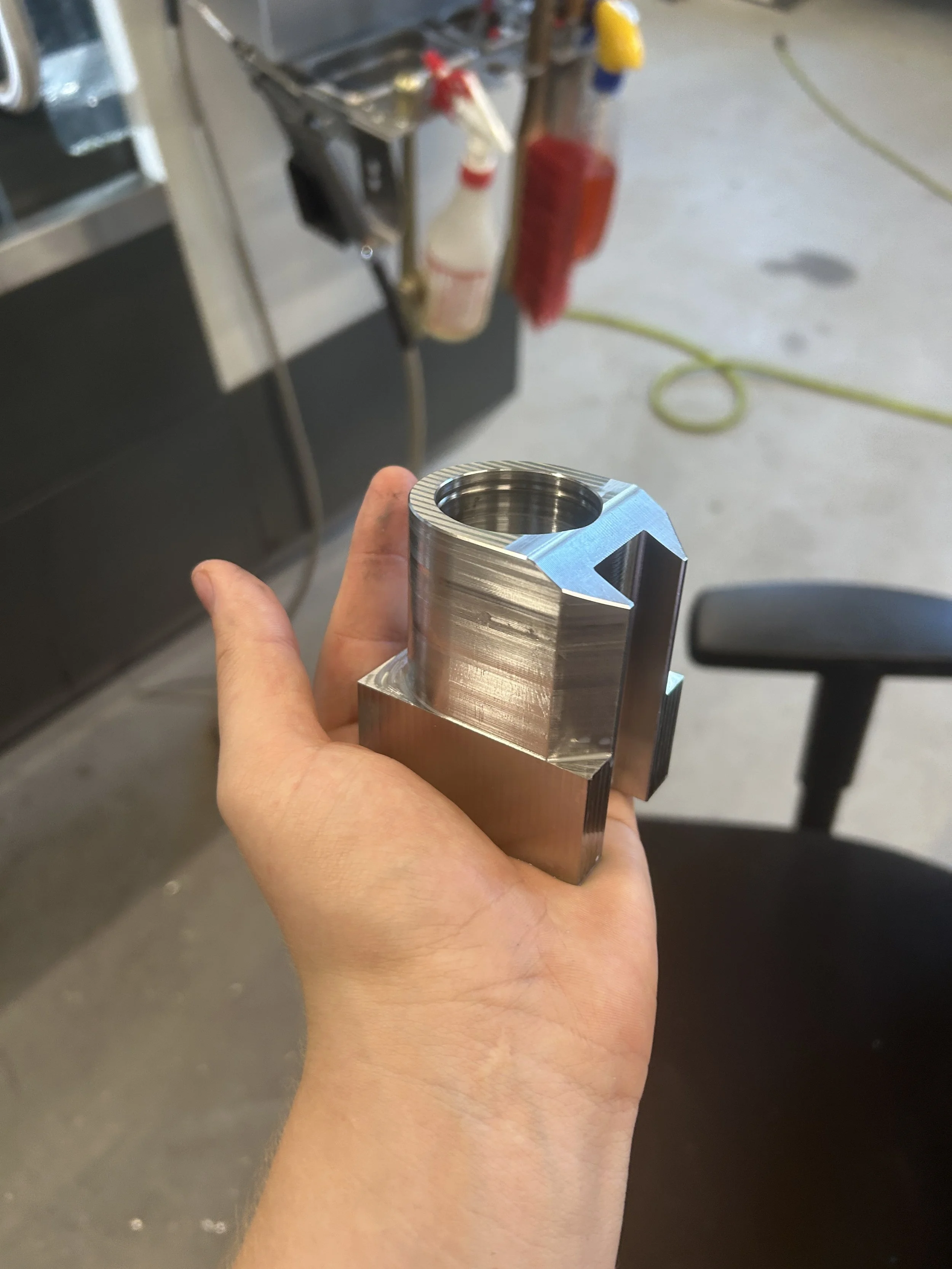
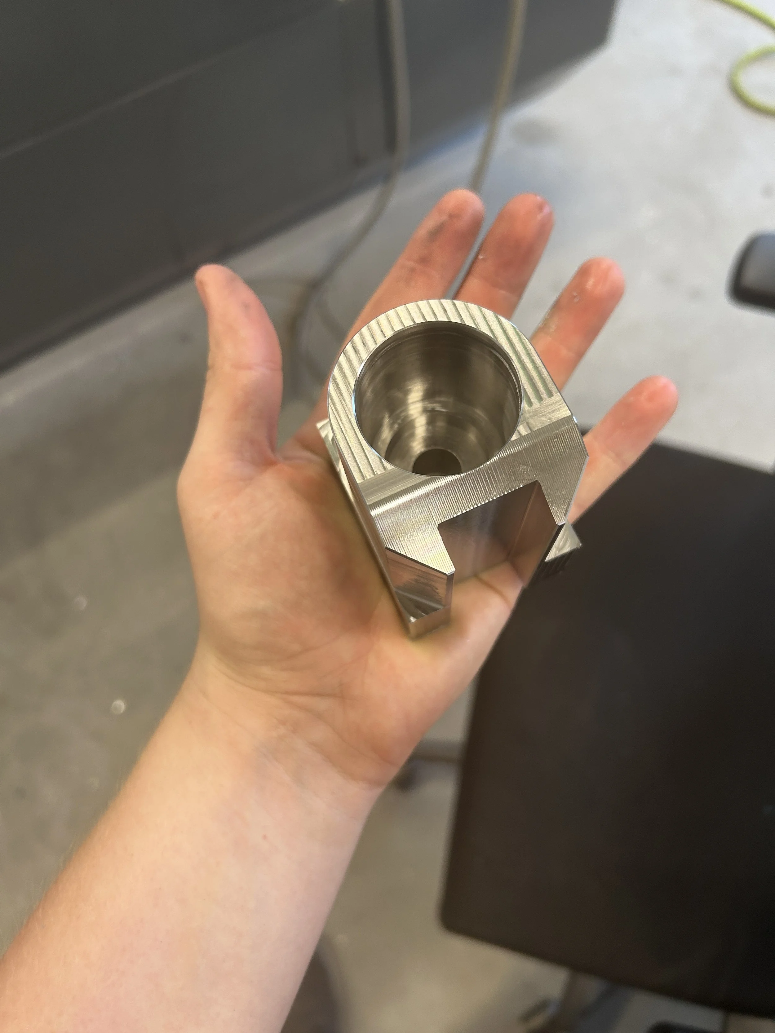
Upper Bushing Holder
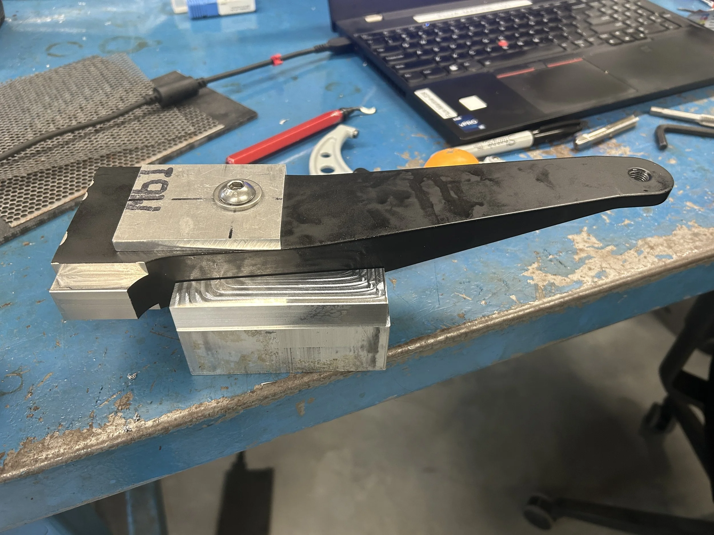
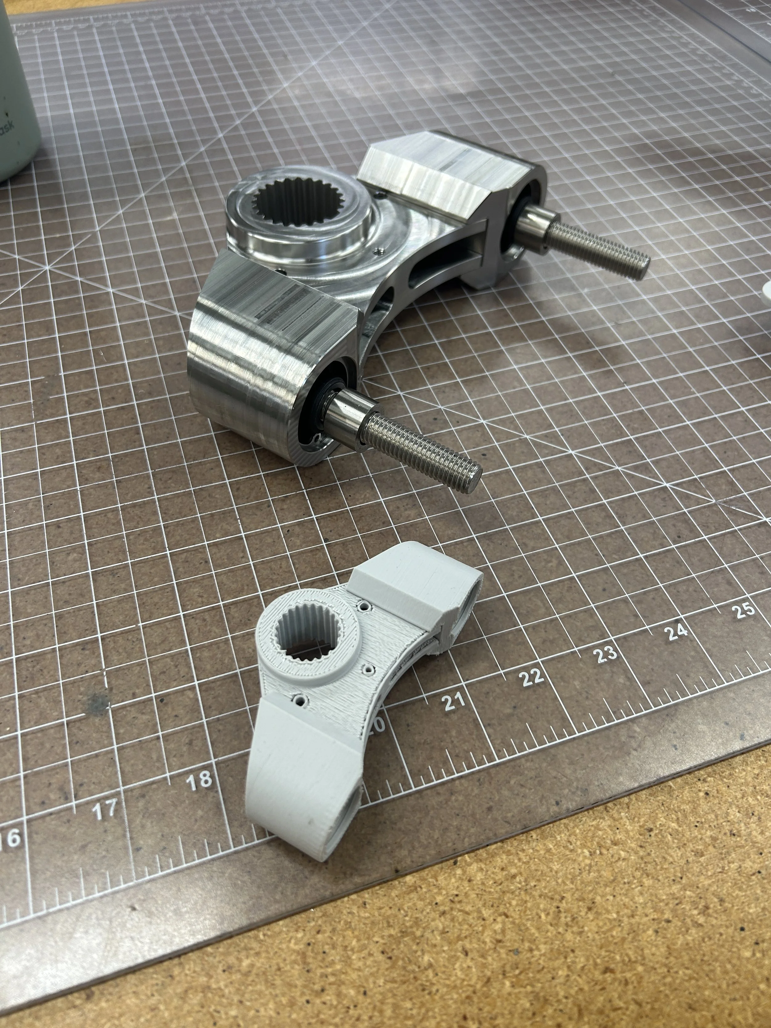
Upper Steering Arm Modification
Upper Assembly/Inspection/Welding Drawing
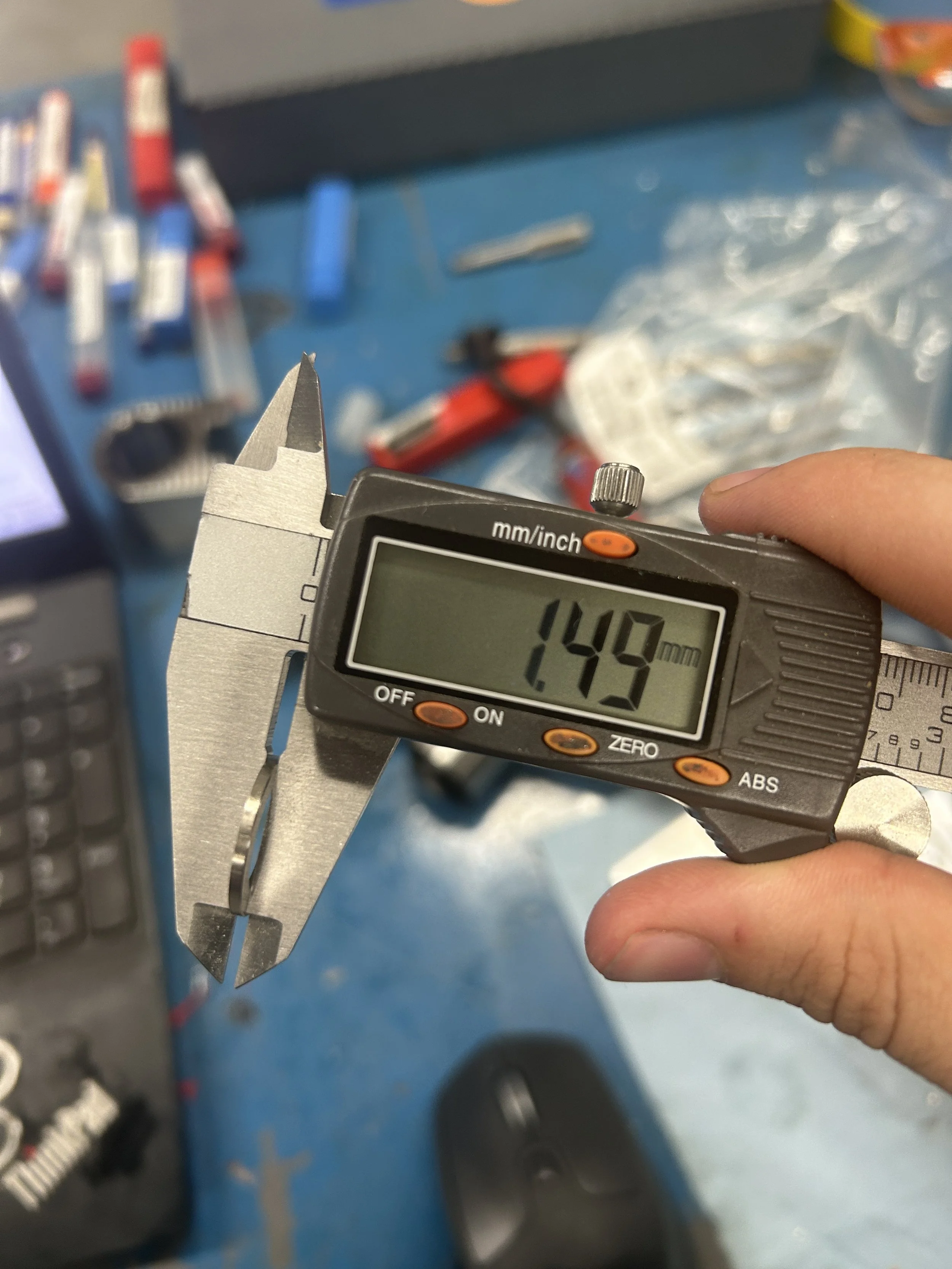
Upper Hardware Stackup
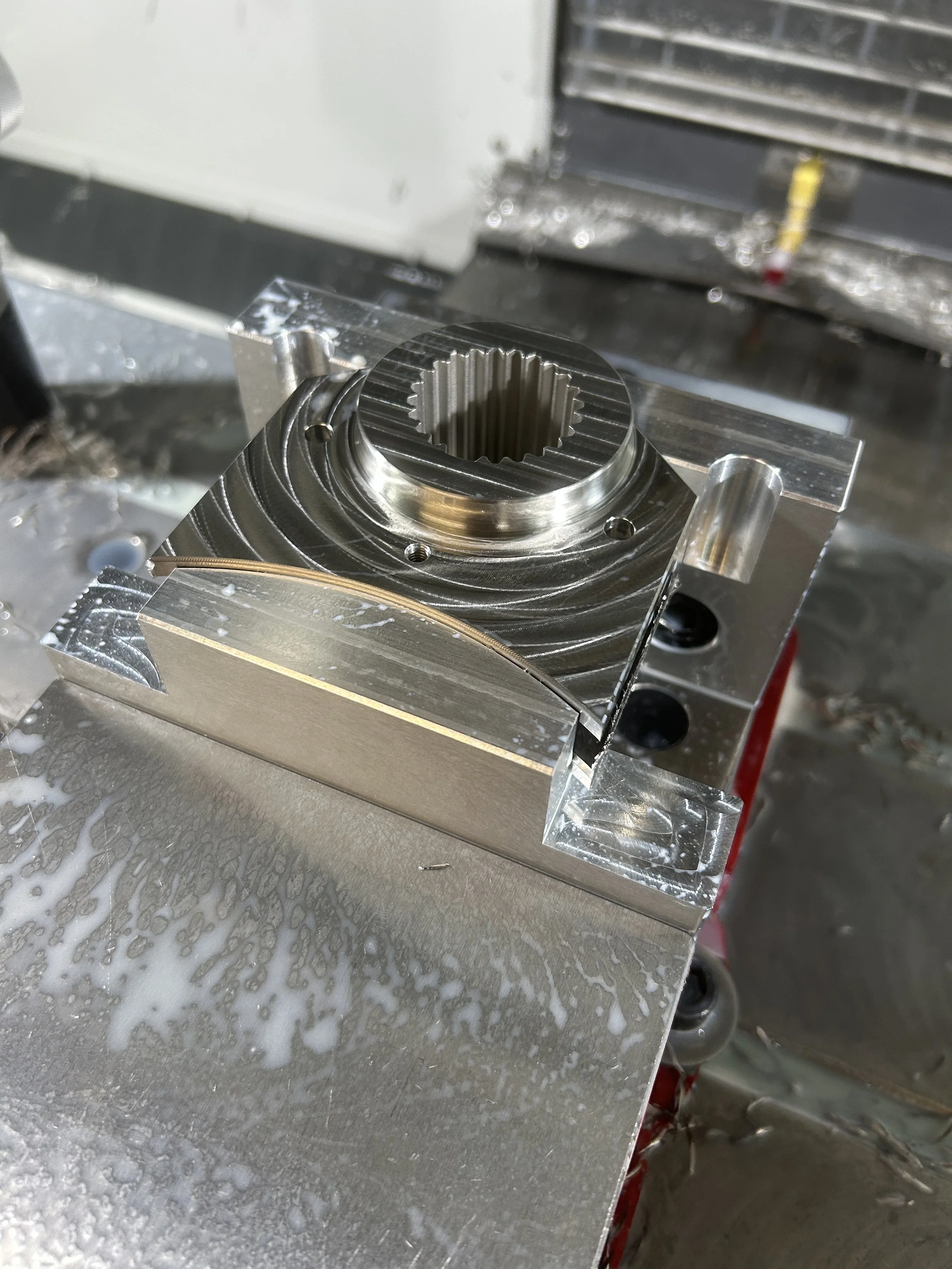
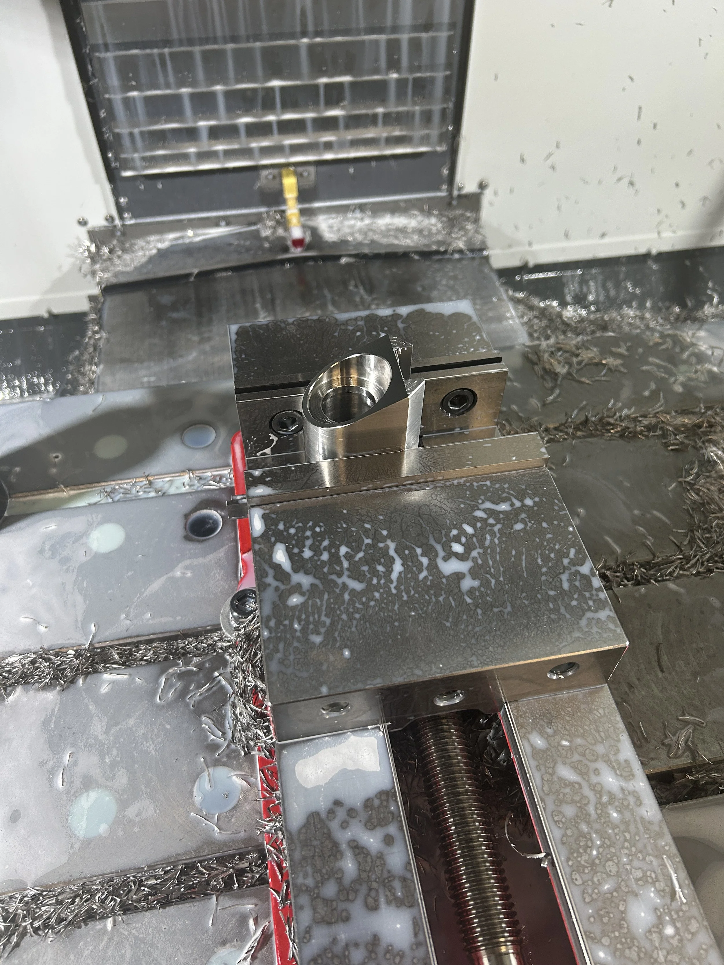
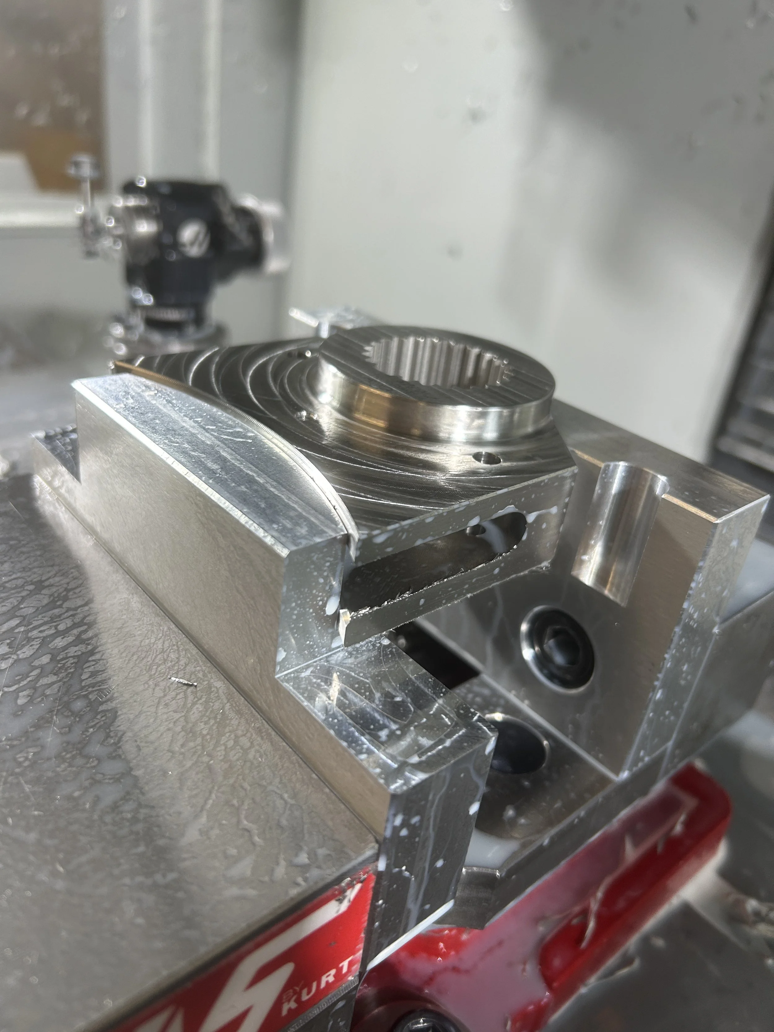
Machining
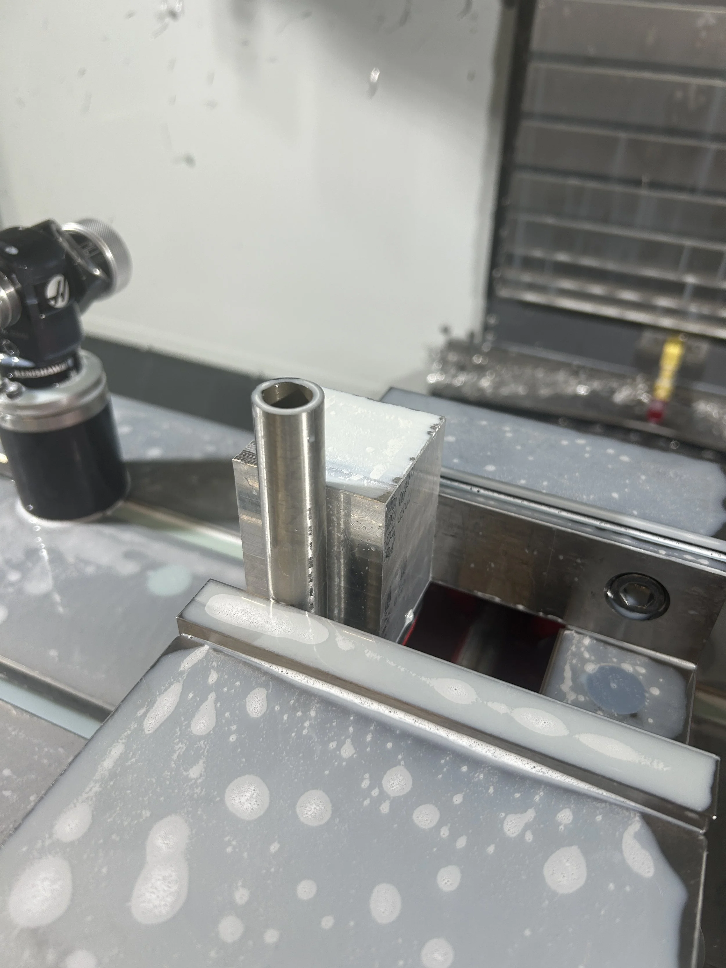
4FL Carbide AlTiN Endmills
Carbide AlTiN Keyseat Cutter
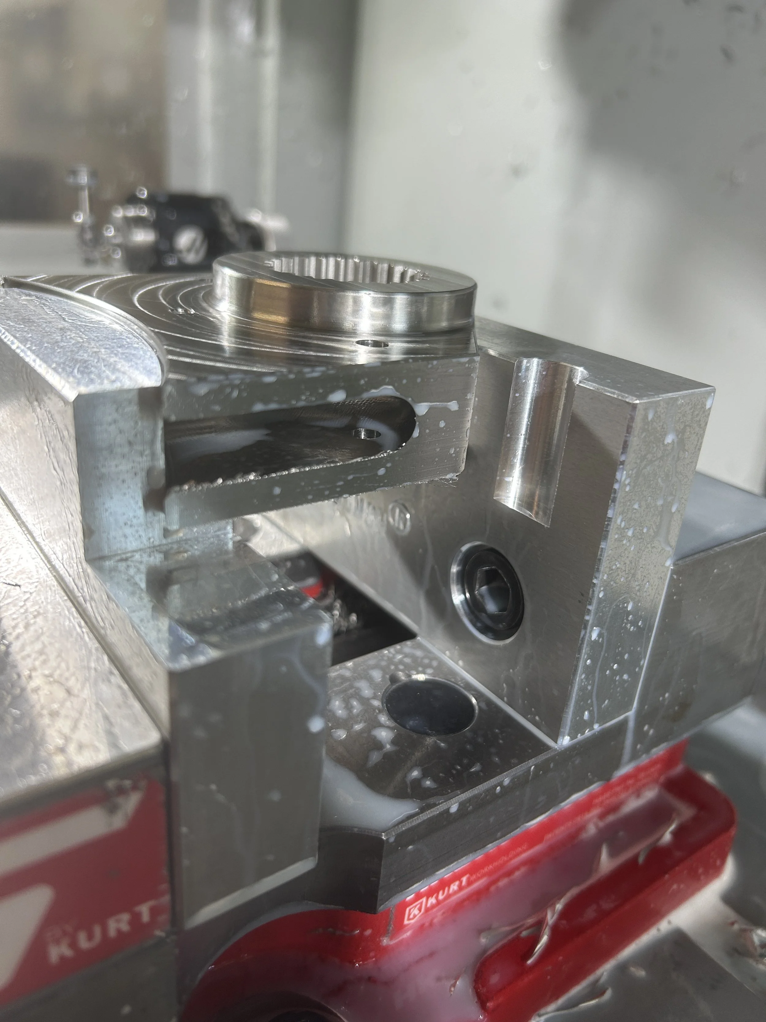
1 Custom Fixture Plate (Steering Arm)
1 Set of Soft Jaws (Bottom Connection)
6 316 SS Components
Problem: “Northeast” XSF
A boat judged qualitatively unacceptable for noise and vibration at the helm on its current 3-blade propeller.
Reference: “Engineering” XSF
Judged acceptable, so it became the baseline platform for three mounting-isolation treatments intended to push further in that direction.
Objective
Quantify sound and vibration on both boats and identify the sources. Test several motor modifications. No compliance thresholds apply. All tests were a quantification exercise; no pass/fail evaluations.
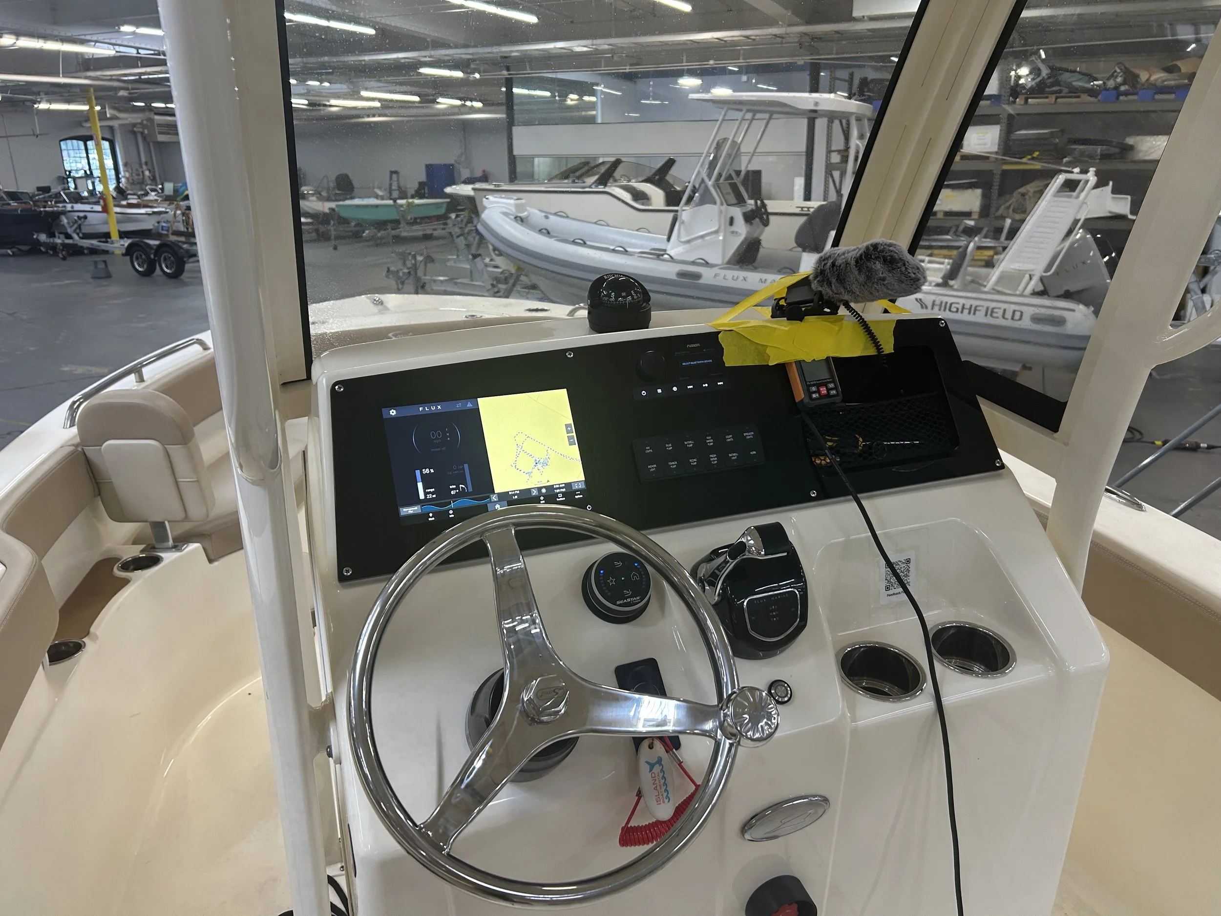
Test 2: Accelerometer / Contact Microphone Vibration RMS & Frequency Analysis
Quantify structure-borne vibration and identify dominant tonal contributors using accelerometer and contact-microphone RMS data, plus frequency-domain analysis of recorded audio (.wav) samples.
Materials
accelerometers: belt housing, motor, and transom
2 contact microphones: belt housing and motor (co-located with the corresponding accelerometers)
1 interview microphone, positioned near the operator
Data acquisition system
Soundboard
Digital Audio Workstation (DAW)
Analysis software for RMS vibration and frequency-domain processing
Test Setup
Sensor locations set: accelerometers and contact mics beneath the cowlings and an operator-position interview mic.
Flux affixed the contact microphones with flashing tape and the accelerometers with VHB and placed the interview microphone near the operator before data collection.
Procedure
Mount the three accelerometers and two contact microphones.
Position the interview microphone near the operator.
Operate through the same duty-cycle throttle points used in Test 1 (idle, 40%, 60%, 80%, WOT).
Log time-domain acceleration, contact-microphone signal, and interview-mic .wav recordings simultaneously at each throttle point.
Run a frequency-domain analysis on each recorded channel to identify dominant frequency peaks.
Compare identified peaks across sensors and against known excitation orders (shaft rotational order, prop blade-pass frequency).
Use this comparison to attribute tonal content and localize its source.
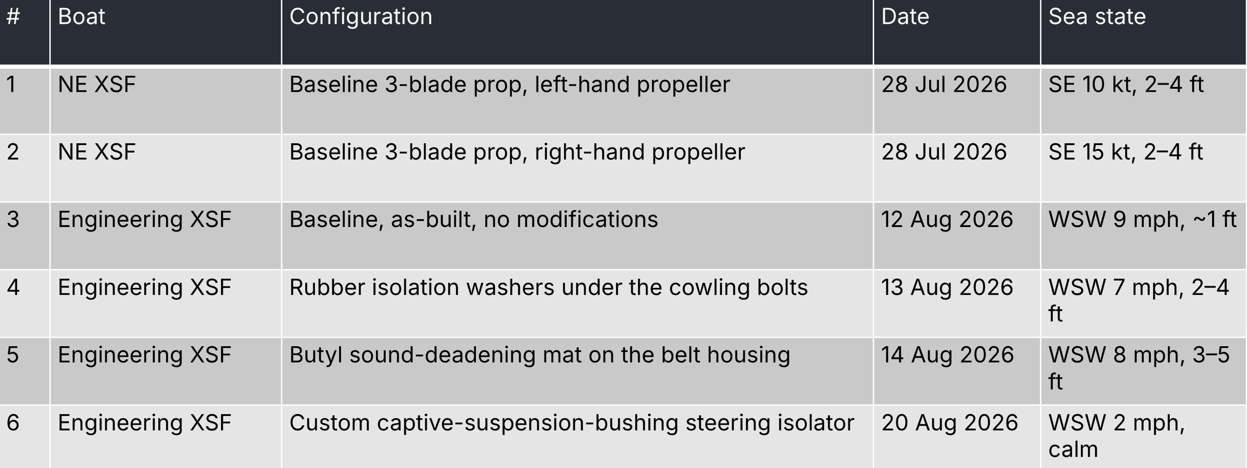
Configuration matrix for testing
Suspension Bushing Isolators
Many OEMs use captive automotive suspension bushings in their steering column mount to isolate their outboard’s vibration and prevent it from reaching the transom. I set out to implement this mounting style on the Flux system to see if it had any merit for an electric motor.
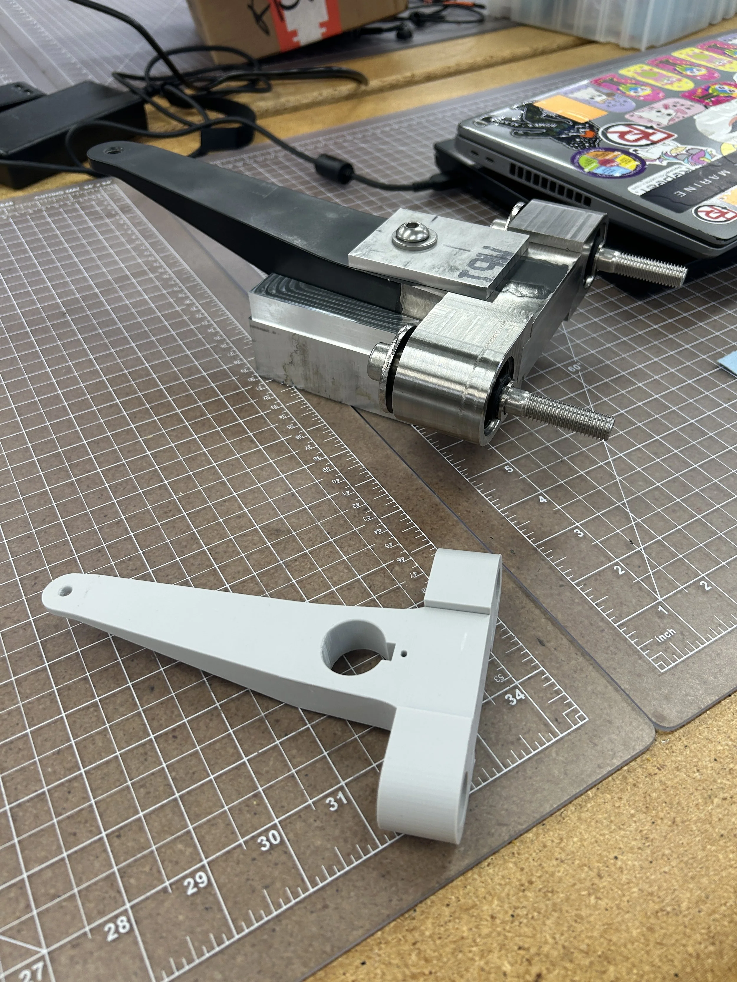
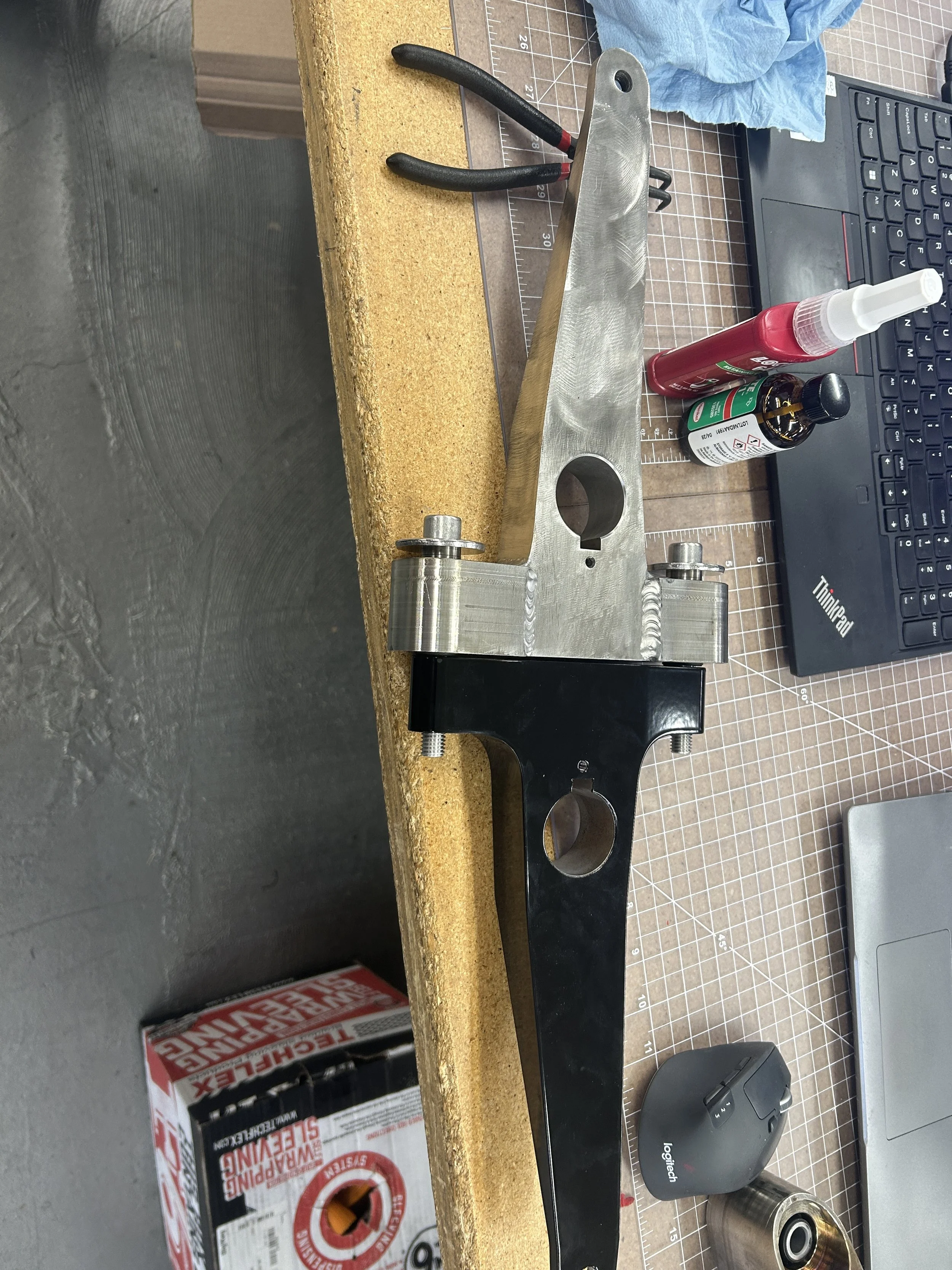
Assembly
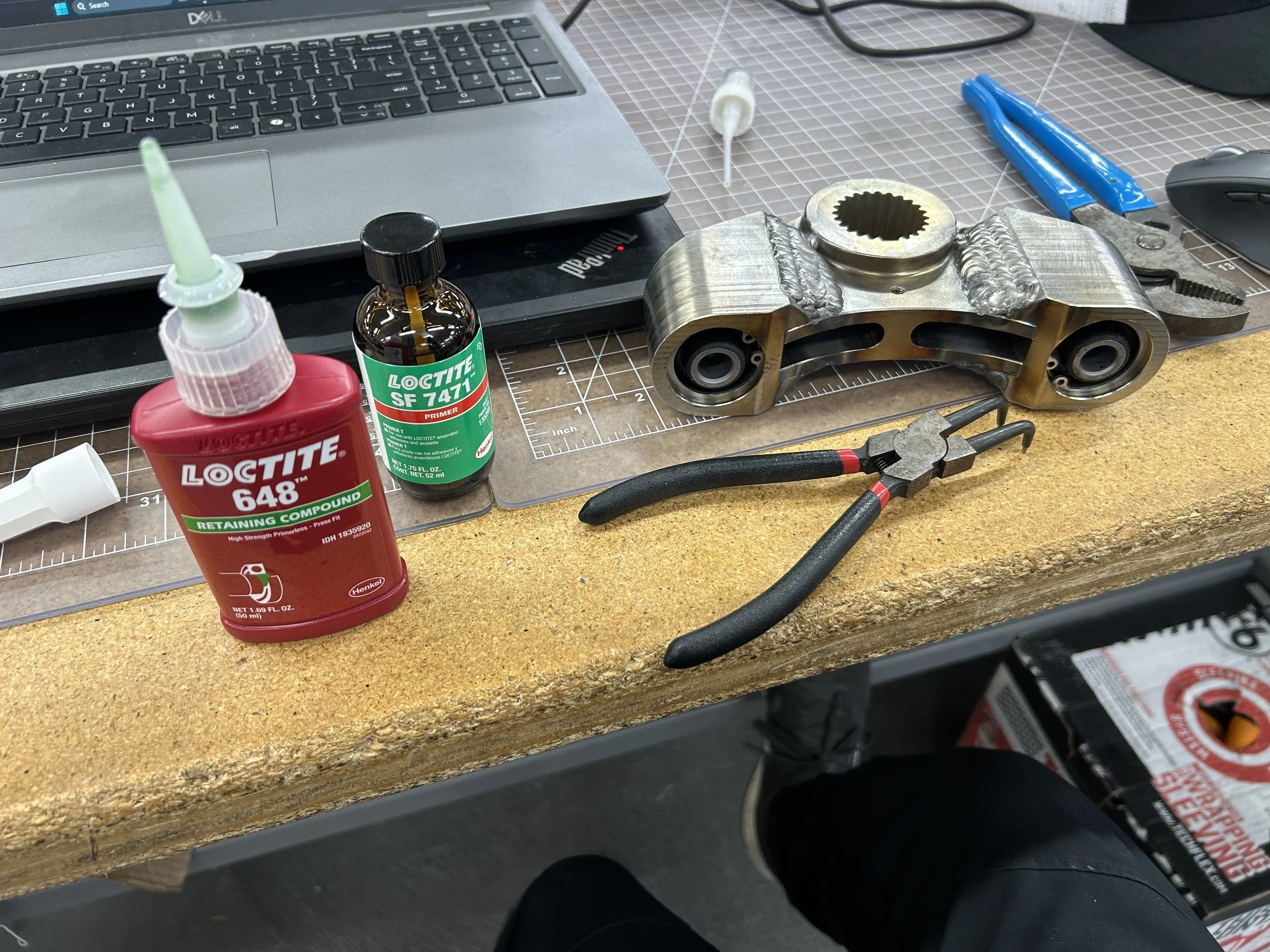
TIG Weld (done by another Flux employee)
Loctite retaining compound with primer for bushings
Motor disassembly and installation
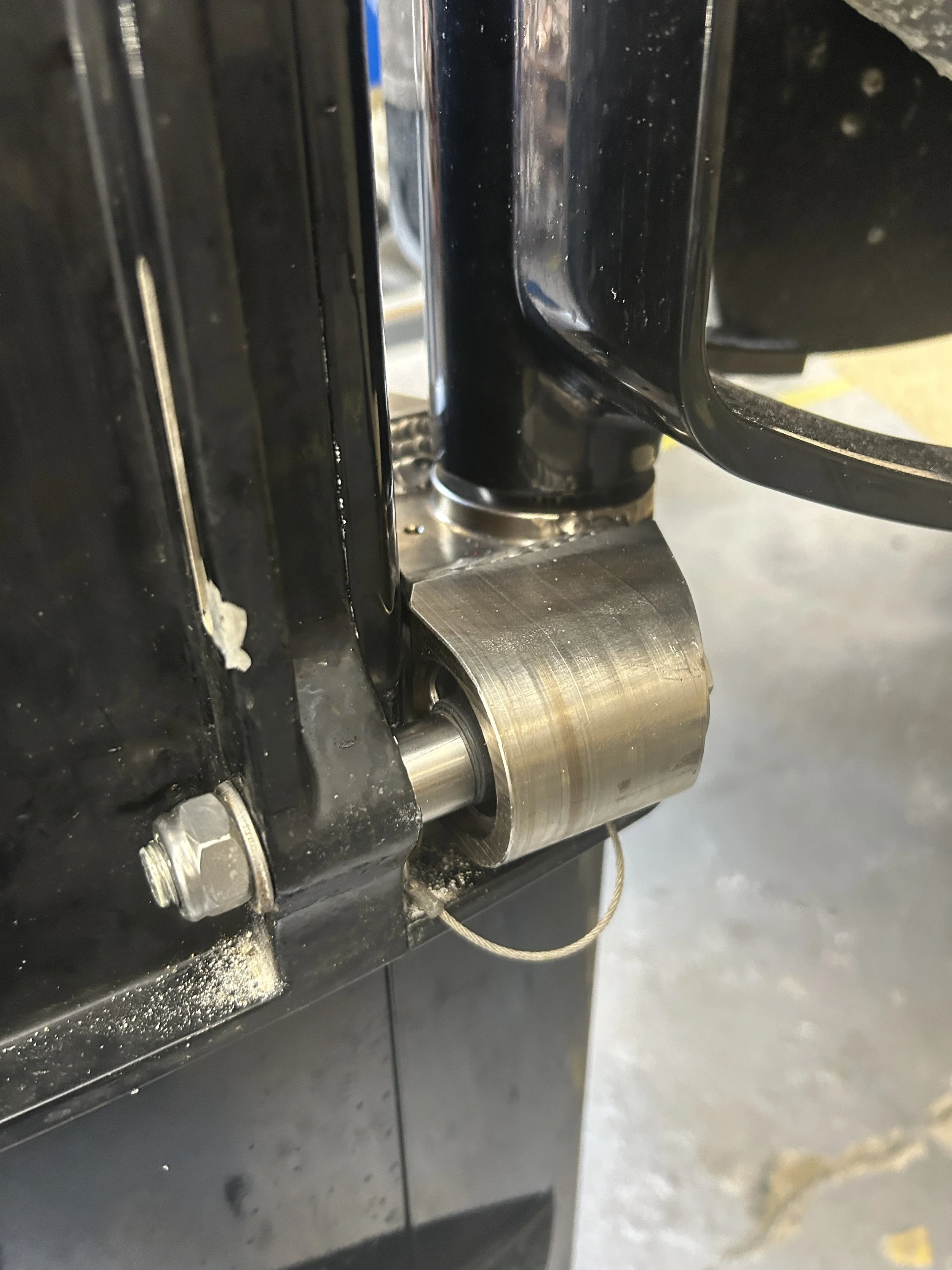
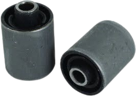
Control arm bushings
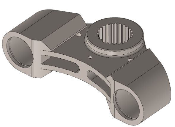
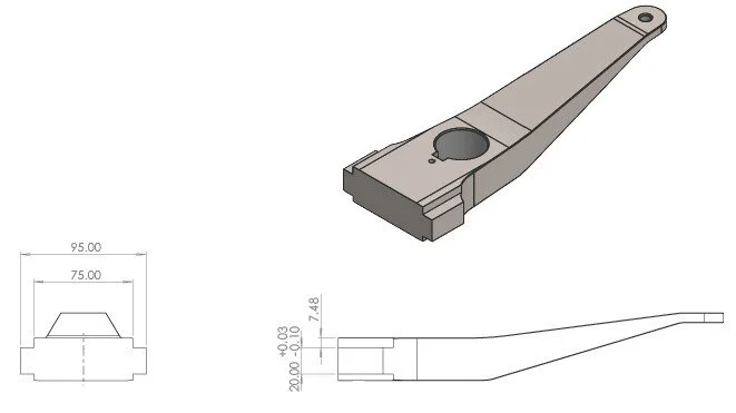
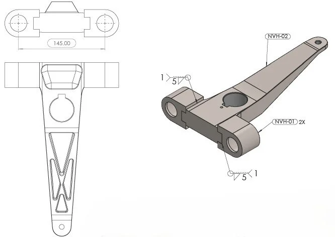
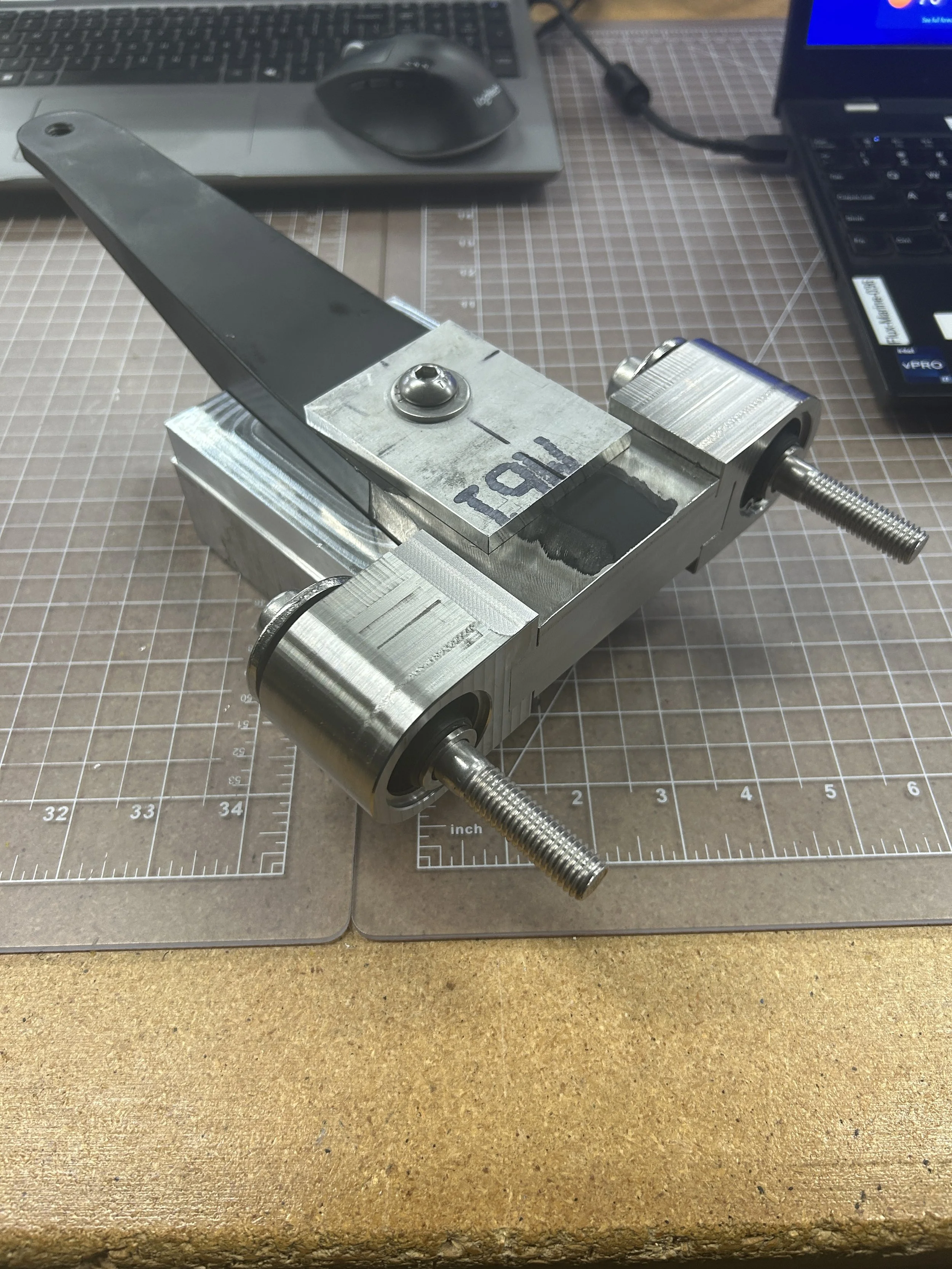
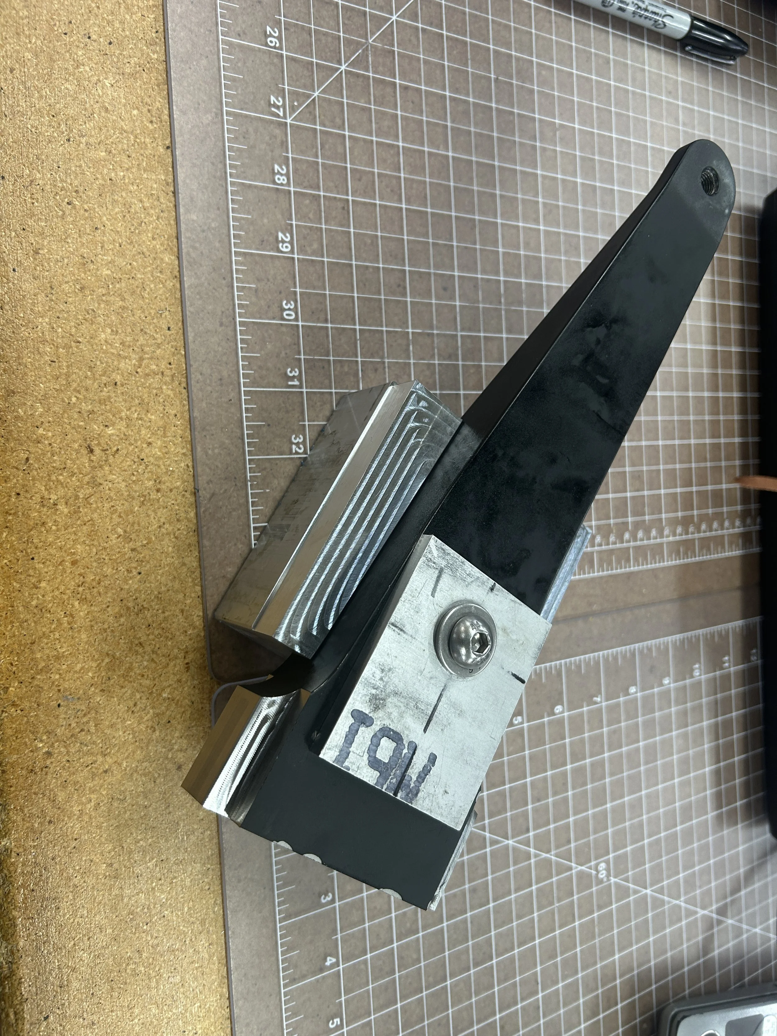
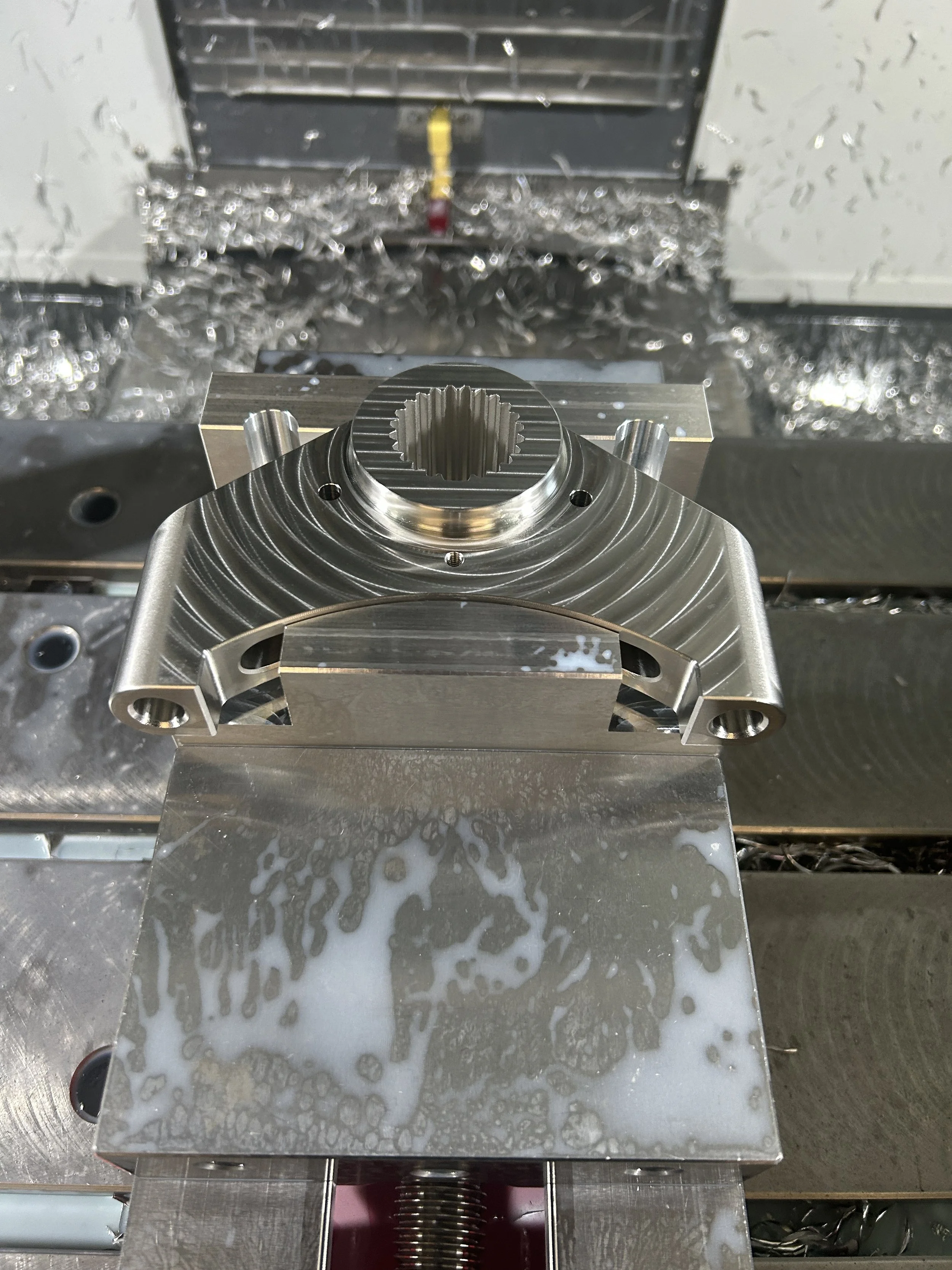
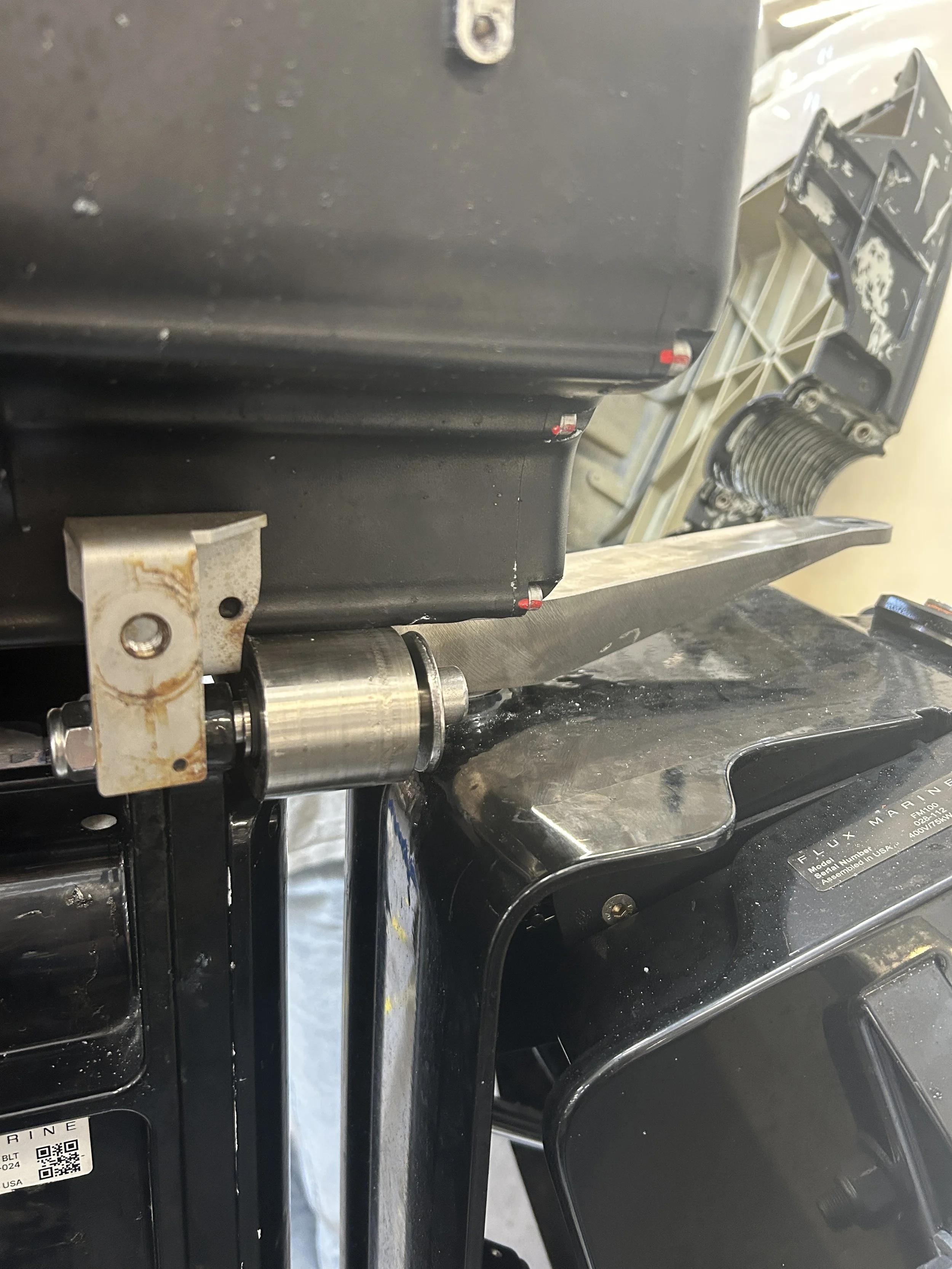
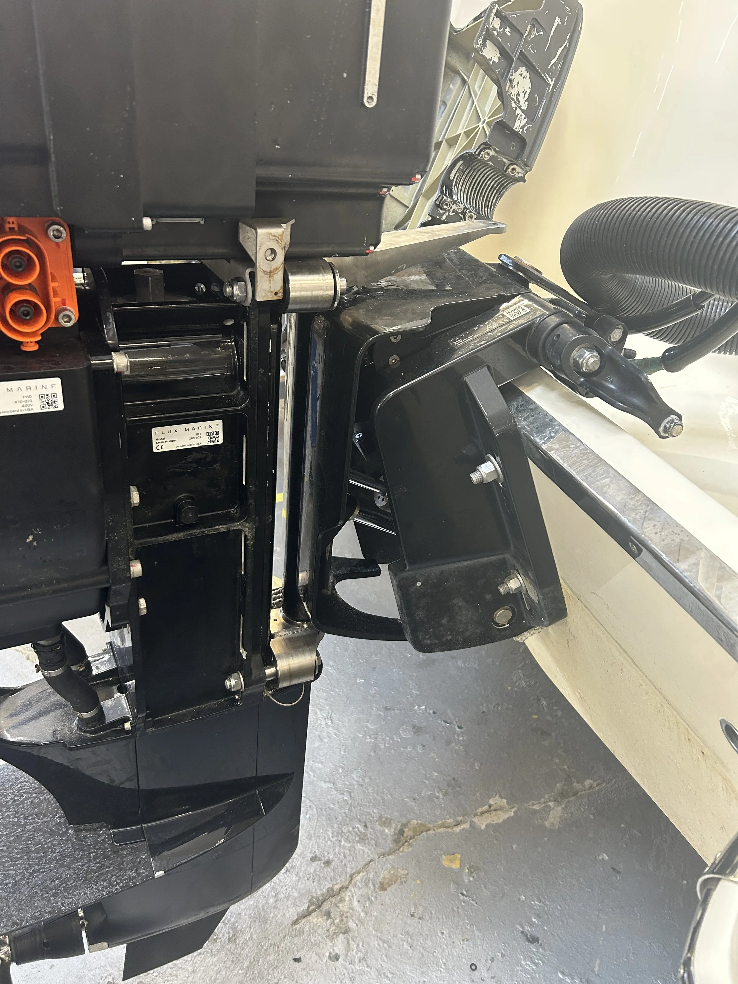
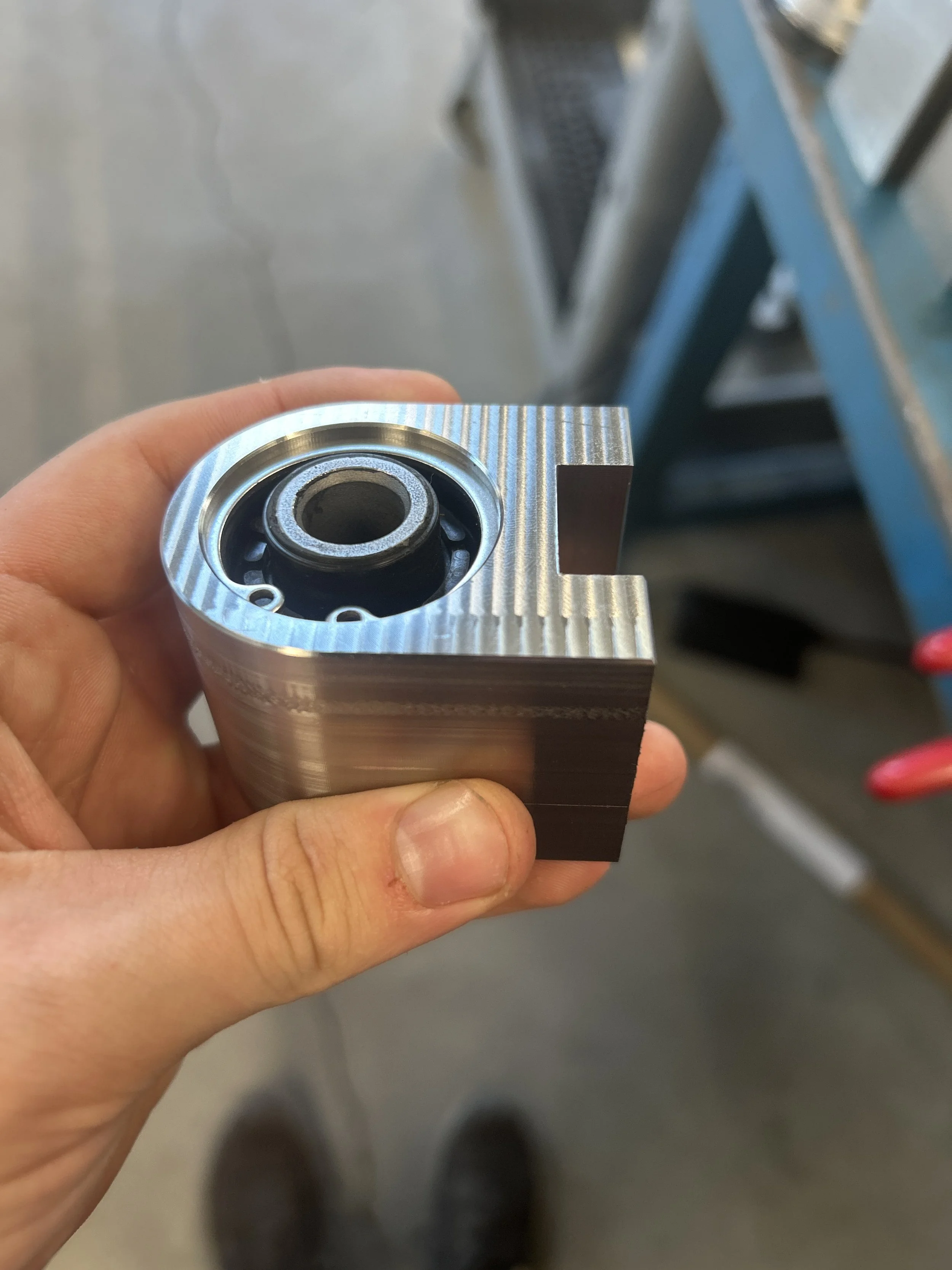
Because of the short timeline for this project and the complexity of the existing components, I decided to modify Flux’s steering components to hold the bushings rather than create new ones. My design cuts off 2 bolt holes on the upper and lower steering connections and replaces them with 4 new welded bushing holders, all 316 SS, including weld filler.
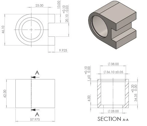
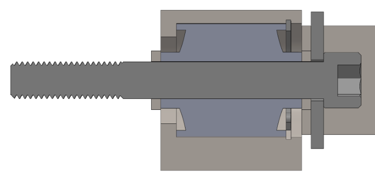
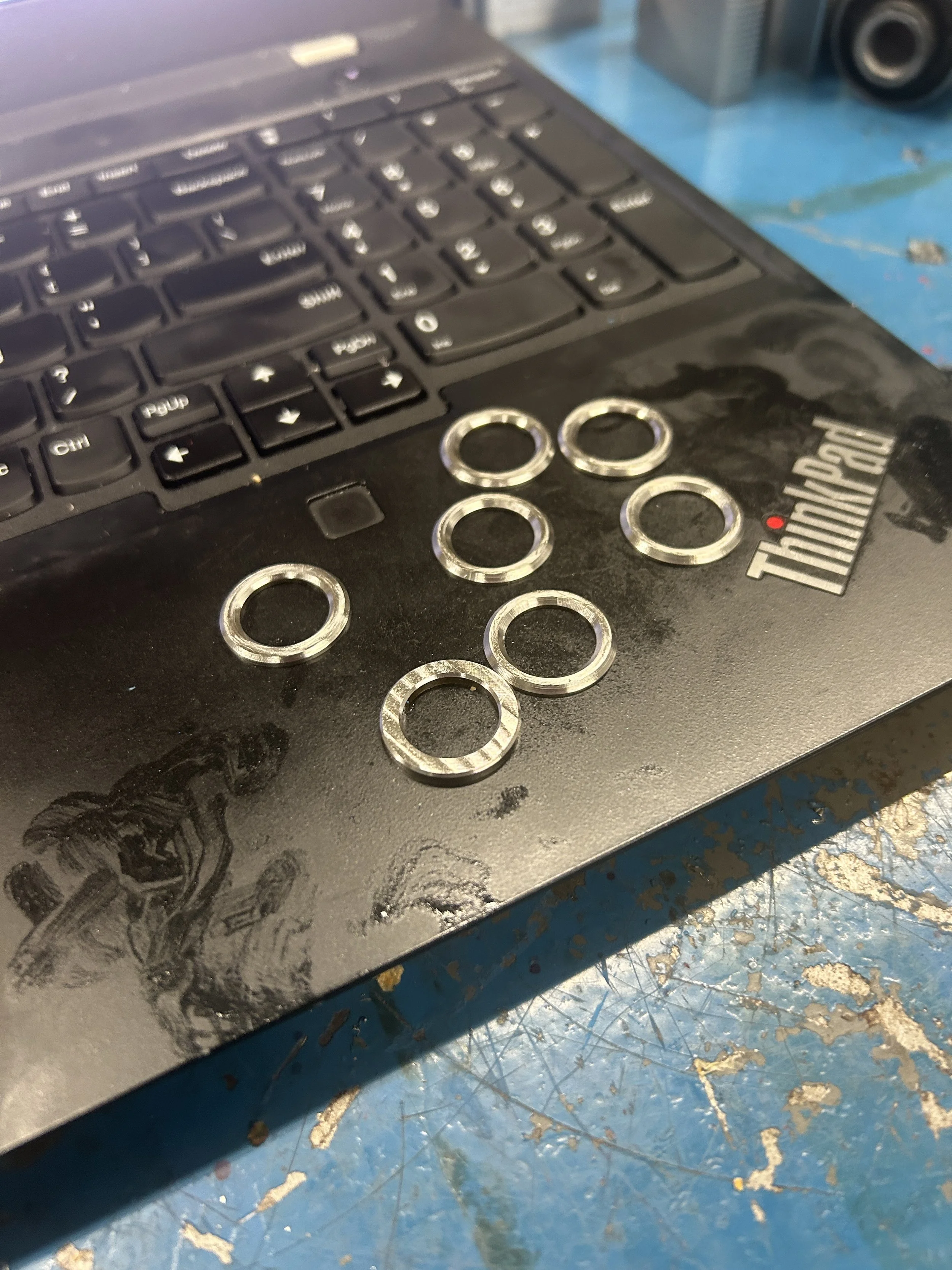
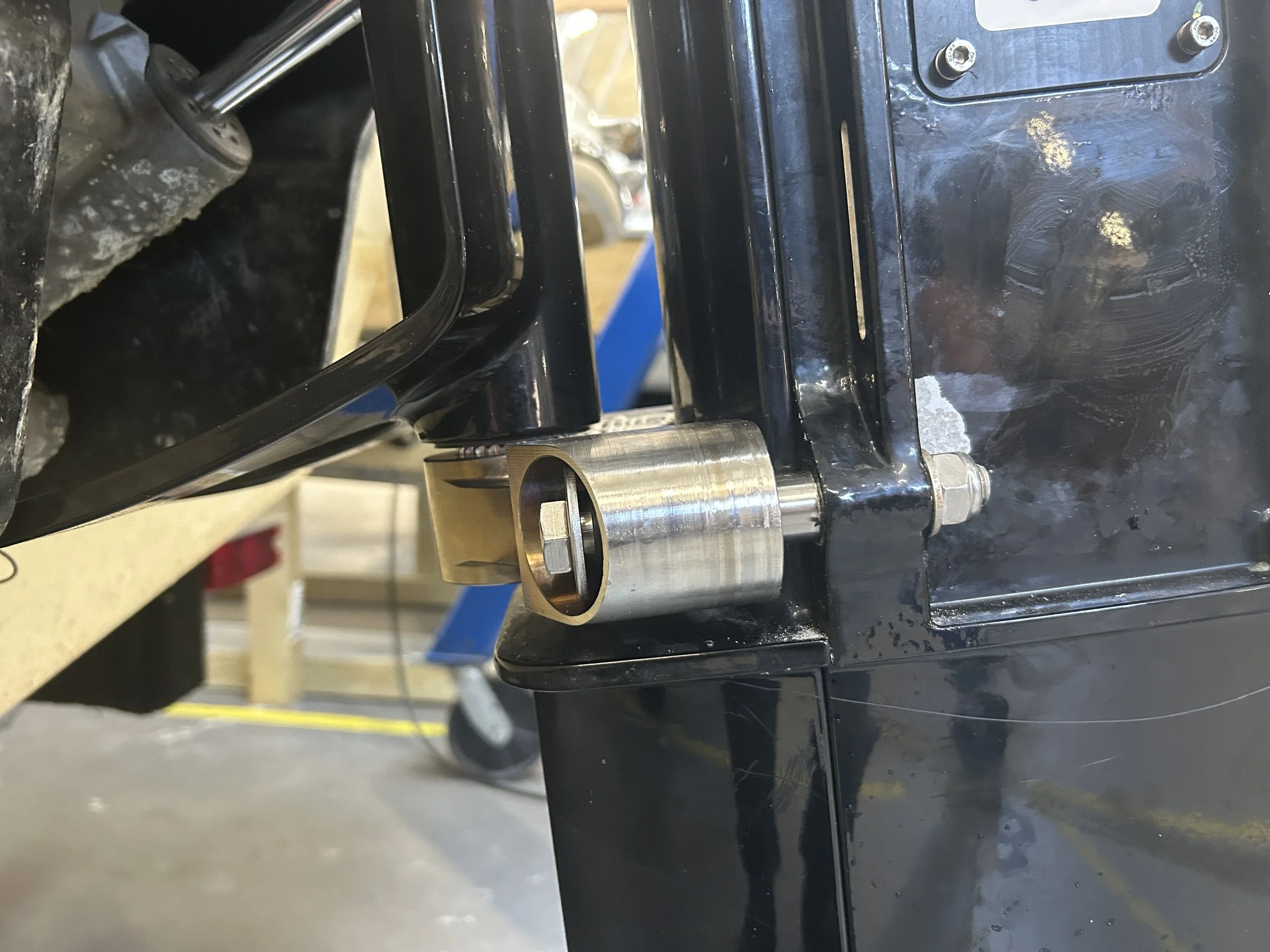
For bushing retention, the custom holders had precise bores to create a slip fit with the bushing OD, leading to a much more compact profile than a bolted clamshell. The primary axial retention method was Loctite retaining compound, supported by a secondary internal C-clip retaining ring. The last resort was an oversized washer in the hardware stackup. All of these methods had a FoS >2 against the maximum theoretical thrust and lateral loading of the motor based on a bollard pull test of the Flux system. Additionally, for packaging, the bushings are installed on the transom side of the steering connection rather than the motor side.
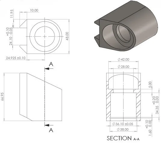
Lower Bushing Holder
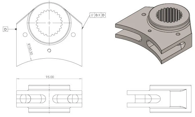
Lower Steering Connection Modification
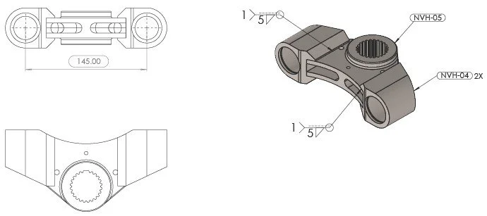
Lower Assembly/Inspection/Welding Drawing
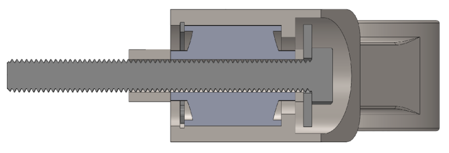
Lower Hardware Stackup
Findings
Drivetrain signatures
By only having the motor RPM, acceleration data, and sound recordings, it was possible to reverse-engineer both the drive reduction and the exact sprocket tooth counts in the driveline of the motor.
Not only is this just a cool phenomenon, but it also gives insight into where noise and vibration are originating from in the Flux system.
Belt Drive Reduction
Motor speed divided by the measured prop-shaft line returns the drive ratio in the RMS vibration data. Twenty-one independent determinations across all six configurations have a mean measurement within 0.5% of the drive reduction.
Therefore: Propeller Shaft
The synchronous belt cannot slip, so the ratio equals the pulley tooth ratio exactly. Recovering it from the vibration data confirms the line is genuine prop-shaft rotation, not a coincidental frequency, and is likely a main contributor to operator-perceived vibration on the Flux platform.
Pulley Tooth Counts
Many acoustic peaks fall on integer multiples of motor speed, and the greatest common divisor equals the motor sprocket tooth count at every speed in all six configurations.
Therefore: Belt Tooth Mesh
The tone the operator hears at WOT is likely belt mesh with the sprockets, not the propeller.
NVH Conclusions and next steps
Engine modifications should target root causes
No modifications had an impact distinguishable from measurement variability.
Most of the modifications targeted isolation rather than directly addressing the identified problem areas. Modifications like the prop swap and butyl mat had larger impacts, but not necessarily positive ones.
Two sources
The operator feels the propeller through the deck and hears the belt through the air. They are independent problems and need separate work.
Work the belt for noise
Belt tension, pulley alignment, tooth profile, and pulley condition.
Work the propeller for vibration
Blade loading and blade condition. Motor rotor balance contributes nothing measurable at any speed in any configuration, so it is not worth pursuing.